The view menu contains useful functionality for modifying the views or changing what content is shown in a view.
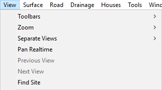
Here you will find a list of design toolbars that you can activate in the current view, allowing you to activate a specific toolbar from the menu.
For an overview of the various design toolbars available in Site3D see The Design Toolbar help page.
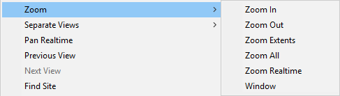
The functionality of many of the zoom tools available in this menu are also available in the View Toolbar.
This menu option will will zoom the view in by a small amount.
This menu option will zoom the view out by a small amount.
This menu option will activate zoom the view so that the site extents are visible. By default the site extents match the drawing extents, so the default behaviour will be the same as Zoom All. However, you can set the site extents from the Window Menu, using the Set Extent to Current View menu option.
This menu option will activate zoom the view so that the entire drawing is visible.
This tool will allow you to zoom the current view precisely based on the vertical movement of the mouse.
![]() When selected you will see the cursor icon change to the realtime zoom cursor. Click and hold the left mouse button and drag the mouse up or down to interactively zoom the current view in or out.
When selected you will see the cursor icon change to the realtime zoom cursor. Click and hold the left mouse button and drag the mouse up or down to interactively zoom the current view in or out.
This menu option will activate the Zoom to Region tool, which will zoom the view so that the selected region fills the view window. This tool can also be accessed from the View Toolbar.
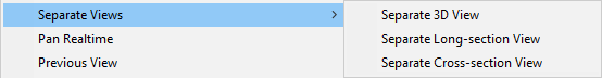
Under the Separate Views option in the view menu you will find the following options in a further menu: Separate 3D View, Separate Long Section View, and Separate Cross Section View. These allow you to open a view externally to the main Site3D window, the separate views will act like independent windows within the operating system. Separating a view will allow you to use the operating systems ability to dock and tile windows, for example this will allow you to have Site3D full screen on your primary monitor and have another view full screen on another monitor.
This option is only available in plan view, when selected this will activate the Pan tool, allowing you to grab and move the view using the mouse cursor. This tool can also be accessed from the View Toolbar.
This menu option will modify the view to match a previous view after a zoom command was used.
The Find Site facility is very useful when you load a drawing which appears blank on the screen. This is usually due to the drawing's extents being huge in relation to the area of interest. The drawing appears to be blank because the useful drawing is so tiny in relation to the extents that it is hidden within a single pixel on the screen.
The Find Site facility will examine the imported drawing entities to work out the likely area of interest and will zoom the display to show it.
Note: Once you have found the site with this option, it is generally useful to then use the Surface->Delete/Crop Region... facility to reset the drawing extents to the useful site.
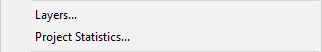
This menu option will open the project layers window. See the Layers Window help page for more information.
This menu option will open the project statistics window, shown below.
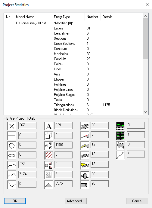
The Project Statistic window shows you the number of different entities that appear throughout the site.
At the top is a list of models which breaks down into the entity types and specifies the number and additional details for each entity.
At the bottom is a combined total for each entity next to the visual representation of the entity. Hovering over the images will show a tool tip which specifies which entity the image corresponds to.
This sections toggles on/off different view settings.
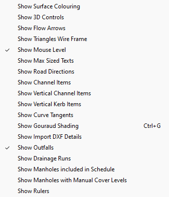
Show Surface Colouring: This option toggles the display of the survey surface in plan view. By default the surface is coloured with high points drawing in orange and low points drawing in blue. You can modify how the surface is coloured using the Model Colour Properties.
Show 3D Controls: This option is only available whilst the 3D view is active and toggles the 3D control panel window, providing a set of controls to alter the 3D view. For more information see the 3D Controls Window help page.
Show Flow Arrows: This option toggles the display of flow arrows on the current survey, the arrows colour indicates the gradient with arrow pointing in the gradient fall direction.
Flow arrow gradient to colour key| 1:10 or steeper | |
| 1:10 -> 1:20 | |
| 1:20 -> 1:50 | |
| 1:50 -> 1:80 | |
| 1:80 -> 1:100 | |
| 1:100 -> 1:130 | |
 |
flatter than 1:130 |
Show Triangles Wire Frame: This option toggles the display of the triangle wire frame of the survey triangulation.
Show Road Directions: This option toggles the display of arrowheads along centrelines which indicate the road direction, pointing from low chainage to high chainage.
Show Channel Items: This option toggles the display of channel items. Coloured blocks will be drawn along the centreline to indicate different channel items.
Show Vertical Channel Items: This option toggles the display of vertical channel items. Lines will be drawn at intervals along the centreline to the channels with arrows pointing toward the channel for a transition to a lower crossfall, and arrows pointing from the channel to the centreline indicating a transition to a greater crossfall.
Show Vertical Kerb Items: This option toggles the display of vertical kerb items. Red lines will be drawn either side of the channel along the section where there is a vertical kerb transition.
Show Curve Tangents: This option is only available in plan view and toggles the display of curve tangents. Gray lines will be drawn showing the two tangent lines that intersect to the curve IP point.
Show Gouraud Shading: This option is only available whilst the 3D view is active and toggles the shading method of the triangulation. Gouraud shading is a lighting method which interpolates across the surface of the triangles, giving a smoother appearance to the triangulation. The issue with this method is that the triangles blend together and the surface can become less distinct.
Show Import DXF Details: This option toggles the display of DXF importing information. A window will appear showing a log of information when you are importing a DXF file.
Show Outfalls: This option is on by default, selecting this option toggles the highlighting of outfalls in the drainage networks. Outfalls will be highlighted with a green circle.
Show Drainage Runs: This options toggles the highlighting of runs in the drainage networks. Drainage will be coloured according to the run number, allowing you to see the drainage runs of a network at a glance.
Show Manholes included in Schedule: This option is only available in plan view and toggles the highlighting of manholes which have the "Included in schedules" flag ticked in the Manhole Properties. A yellow triangle will be drawn behind manholes. Note this option will turn off "Show Manholes with Manual Cover Levels".
Show Manholes with Manual Cover Levels: This option is only available in plan view and toggles the highlighting of manholes which have the "Manual" flag ticked in the Manhole Properties. A yellow triangle will be drawn behind manholes. Note this option will turn off "Show Manholes included in Schedule".
Show Rulers: This option is only available in plan view and toggles the drawing of rulers at the edges of the view. The rulers annotate the coordinates for the x and y axis.
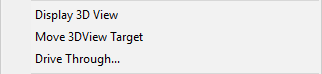
This option will open the 3D view window allowing you to view your site in 3D. You can also open the 3D view by using the 3D view button in the model view toolbar.
This option will open Google Earth if installed and set the view to the site location.
This option is only available whilst the 3D view is active and will bring up the drive through window. You can select which road you want to move along, set the height from the road surface you want the view to be, and the speed to move along the road. Below that is a slider which indicates the position along the road, clicking the play button will start moving the camera along the centreline. Note: This is not simulated vehicle tracking and is just another way of viewing your site in 3D.
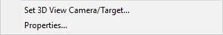
This option is only available whilst the 3D view is active and will allow you to place points in the plan view to set the camera position and target position. The camera position will be the place that you are viewing from in the 3D view and will be indicated as a green cross in the plan view. The target position will be the point of interest that you are looking at in the 3D view and will be indicated as a red cross in the plan view. The crosses that get drawn in the plan view will disappear once the plan view is moved or zoomed.
This option will open the view properties for the current view. If you are in the plan view you will see the Project Options window appear. In the 3D view you will see the 3D view properties window appear. In a longsection view you will see the Section View Display Properties window appear. In a cross section view you will see the Cross Section Properties window appear.