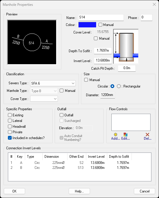
This option shows the properties of a manhole and allows you to modify them.
On the ![]() drainage tools toolbar, click the
drainage tools toolbar, click the ![]() manhole properties button.
manhole properties button.
You will be prompted to select a manhole from the drawing. As you move the mouse cursor the nearest manhole is highlighted. Click to select. The manhole properties window is shown.
Note: To edit the properties of many manholes at once, use the Manhole Properties Schedule.
By default, each new manhole is added as a chamber. Using this dropdown you can alter the type, the currently supported types are:
By default, each new manhole is allocated a name comprising a prefix of either S for storm sewer networks, or F for foul sewer network, followed by the next sequential number for the network. For example, S1, S2, S3, ... S23, S24, and so on. Private manhole labels auto-name with a prefix of PS and PF instead of S and F, so that the adoptable manhole number sequence is not intermixed with private manhole numbers. Both the adoptable and private/plot prefixes are user-configurable. See the Configuration Options for more information.
You can change the name to anything else, as may be appropriate for your manhole. The name may contain spaces, if desired. The manhole name is displayed on the plan view, next to the manhole.
Note: If you want to renumber the entire drainage network, use the Manhole Renumbering facility.
This shows the current phase number for the manhole. Initially, there are is only one phase (0) for all new manholes. You can choose to alter the phase number so that one or more manholes are on different phases so that the manhole schedule and drainage schedule are split out into phases. The phase is a numeric value.
By default the Cover Level is determined automatically. Where the manhole is situated within the designed surface then that will be used for the cover level, otherwise the existing ground surface level is used.
If you need to fix the cover level at a specific value, you can select the Manual option and enter your desired cover level. When the manual cover level is set, it will not change if the manhole is moved to a different location.
This shows the depth-to-soffit of the outgoing pipe of the manhole. This value is often important for determining the manhole construction type. Changing this value will alter the invert level of this manhole.
This displays the current invert level at the base of the manhole. When the manhole is first placed, the invert level is set so that the soffit level of the joining conduits are 1.2m below the design surface at the centre of the manhole (or 0.6m below the existing ground if the manhole is not under the design surface). Altering this value will automatically update the depth to soffit value.
You can enter a different invert level, as required.
Note: Changing the manhole invert level will also change the level of the joining conduits. The conduits join into the base of the manhole, with their soffit levels aligned.
By default the manhole's invert level is set to the lowest invert level of its joining conduits. However, if the manhole requires a catch pit, an additional catch pit depth can be specified. The manhole will be drawn extending below its joining conduits by the given depth.
This shows the current size for the manhole chamber. The size is set automatically, based on the size of the conduits joining into it, and the manhole construction type.
If necessary, you can override the automatically determined size by selecting the Manual option next to it, and entering your preferred size, and/or change between circular/rectangular types.
This section defines parameters for deep bore soakaways, selected via the Type dropdown.
You can choose with design standard you are working to. For example, Sewers For Adoption 6 (SFA 6) or Design Construction Guidance (DGC March 2020). The Sewers Type determines the choice of Manhole Types.
This is a drop-down list of manhole construction types available for the selected Sewers Type. For example, with DCG there are Type A, Type B, Type C, etc.
The manhole construction type will be set automatically to the most appropriate type within the Sewers Type, based in factors such as depth-to-soffit, incoming pipe diameters, benching requirements, rectangular/circular shape, and minimum size requirement.
If necessary, you can override the automatically determined type by selecting the Manual option next to it, and choosing your preferred type from the drop-down list.
This is a drop-down list of manhole cover types available based on the BS EN 124 specification. This set of cover types is based on the covers load ratings ranging from A15, which has a 15kN max load capability, to F900, which has a 900kN max load capability. Below are some suggested use cases:
By default, manholes will use an automatic colour based on whether they are a surface or foul manhole as well as whether it is flagged as part of the private/plot drainage. Tick the Manual checkbox next to the colour picker to have this manhole drawn using the colour shown in the colour picker.
Clicking on the colour picker will bring up a colour chooser window. This allows you to select a bespoke colour for this manhole which will be shown in both the plan and longsection windows.
By default the drainage network is considered to be a new designed system. However, you may want to include some pre-existing manholes from the site. Accordingly, you can select the Existing option to flag the manhole as an existing one.
Note: Flagging a manhole as Existing will force the Manual option for the Cover Level, because the cover level for an existing manhole is normally fixed.
A lateral is generally a connection spurred off a main sewer run, e.g. for later connection to a building's private drainage.
If you set the manhole as a lateral then it is considered not to be part of the main network and will not appear on the manhole schedules.
A lateral will also not be included when the network is exported to other drainage software.
Setting this flag will indicate whether the manhole is Private or Adoptable. This will affect where it is shown on schedules and how it exports out to other systems like Microdrainage.
Setting this flag will indicate whether the manhole will be appear in the schedules, such as the plan manhole schedule.
Every sewer network must have an outfall where the water discharges. Accordingly, you must set one of the manholes in a network as the Outfall.
If Outfall is ticked, you will be able to click the Surcharged option next to the outfall tickbox.
If Surcharged is ticked, you can type in an elevation value to indicate how full of water the outfall is. This is a constant surcharged level that will be used for the full length of any storm simulations. The elevation is an absolute level and not a depth. This option is only available when Outfall is ticked.
When the Outfall option is ticked on, the Auto Conduit Numbering option will be available. When selected, this will automatically generate the run number and conduit index (e.g 2.001) for every pipe directly connected to this outfall.
The conduit numbers are important for exporting to other drainage systems and need to be set in the standard dendritic convention. Should you need to change the run number, untick this option then edit the run number for each conduit that requires alteration in the Conduit Properties.
Note: If Auto Conduit Numbering is not selected on the outfall, then none of the pipes will have their numbers updated if you subsequently make changes to the drainage network, and then it may not export well to your drainage package.
Here you will see a list of the flow controls that have been added into this manhole.
The Add... buttons can be pressed to insert a new flow control into this manhole. The Edit... button can be pressed to edit the properties of a flow control which has already been added to this manhole. And the Del... button can be used to remove a flow control from this manhole.
See the Manhole Flow Controls page for more information.
By default every auto cover levelled manhole is excluded from the final surface as its cover level is determined by the other design items. Whereas, manual cover levels are included by default, you can toggle the Final Surface option to include/exclude any manually set cover levels.
By default every manhole is included in the formation surface. However, you may want to exclude an individual manhole, untick the Formation Surface option to exclude it.
This is a list of incoming and outgoing pipes. The columns are described below:
A manhole can be set as a Headwall in the Type dropdown. It will be shown with a headwall symbol on the drawing.