 button.
The Surface Tools can be used to modify some aspects of an imported model. You can edit 3D points and add or delete 3D lines which define how the 3D surface forms, and you can remove regions of the drawing.
Note: These tools permit you to change the imported data. It is generally recommended that if you think the supplied data is incorrect then you should refer back to the supplier for verification, for example, the original surveyor.
To access the tools for modifying terrain surfaces click the button.
You will see this toolbar appear on the top left of the plan view window:


![]() Add a breakline
Add a breakline
![]() Delete a breakline
Delete a breakline
![]() Add a new point on the terrain
Add a new point on the terrain
![]() Edit a point on the terrain
Edit a point on the terrain
Add a trim line to a surface
Delete a trim line from a surface
![]() Delete a region from the project
Delete a region from the project
![]() Click this button to close the Road toolbar
Click this button to close the Road toolbar
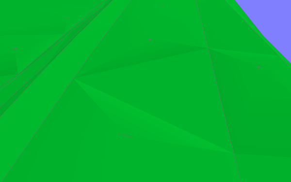
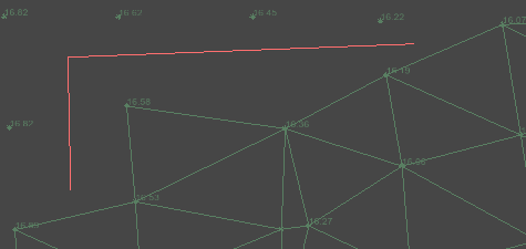
The image below shows a road with a strange surface. The triangles have formed all the way across the road surface in between the 3D points on the centreline. We need to add a breakline between the 3D centreline points to stop this from happening.
To create a new breakline click the ![]() button.
button.
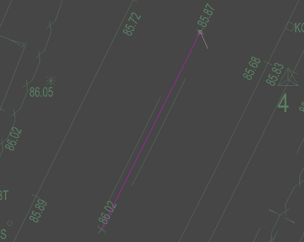
Select a 3D point for the start of the breakline (it will automatically be highlighting 3D points with the 'snap square'). As you move the mouse to pick the next 3D point you will see a line stretching to the cursor position representing the breakline between the two points. Click to select the next 3D point, and so on. When you are finished, right-click the mouse and select Quit Command from the menu, or press the Escape key on the keyboard.
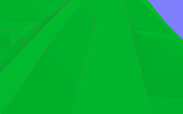
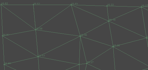
Once finished the new breakline will automatically be added to the 3D terrain and will force the triangles to reform so that no triangles cross any line segment of the new breakline. Obviously this may not be physically possible if you have chosen crossing breaklines so the advice is to not cross breaklines. You can however join multiple breaklines at a 3D point.
This option is for deleting an entire breakline from the current survey.
Click the ![]() delete breakline button.
delete breakline button.
Select the breakline you want to delete (the breakline will highlight as you move the mouse cursor near to it). When you click the mouse the breakline will be deleted and the surface will automatically reform.
After the breakline deletion the drawing will update and items like surface contours and height shading will automatically recalculate accordingly.
If you want to reinstate the deleted breakline, you can click the Undo button.
This option is for adding a new 3D point into the current survey.
To place the points accurately, you can use the various snap options on the snap toolbar, and make temporary construction lines using the construction line toolbar.
To add a new 3D point simply left click once on the plan view to choose the points new location and the following window will appear:
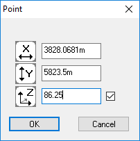
You can now verify and modify the X,Y and Z aspects of the new point. Unticking the box next to the Z level will remove this point from the survey surface. Click OK to insert the new point into the 3D surface.
After the 3D point is inserted the drawing will update and items like surface contours and height shading will automatically recalculate accordingly.
This option is for modifying a 3D point in the current survey.
Select a point from the survey (the points will highlight as you move the mouse cursor near to them). When you click, the following window will appear:
You can now modify the X,Y and Z aspects of the selected point. Unticking the box next to the Z level will remove this point from the survey surface. Click OK to accept the changes to the point.
After the point is modified the drawing will update and items like surface contours and height shading will automatically recalculate accordingly.
Add a trim line to a surfaceThis tool gives you the ability to draw lines over a surface to remove any triangles that it overlaps.
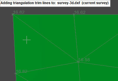
After selecting the tool and the surface to modify, the triangulation of the chosen surface will be displayed, with its title shown below the toolbar. You can change the surface at any time by right clicking and picking the Select Surface option. Click anywhere to start a new line somewhere on the triangulation of a surface:
After clicking you will see a line from the last position to the mouse cursor. You can click again to add the indicated line.
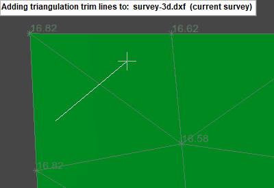
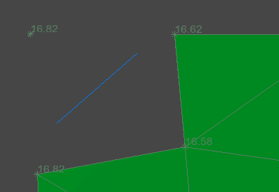
After you are done adding points to the line, right click and select Finish to add the trim line to the model.
If you draw a line which encloses an area, with the start and end point snapped to the same position, any triangles that are inside the loop will be removed:
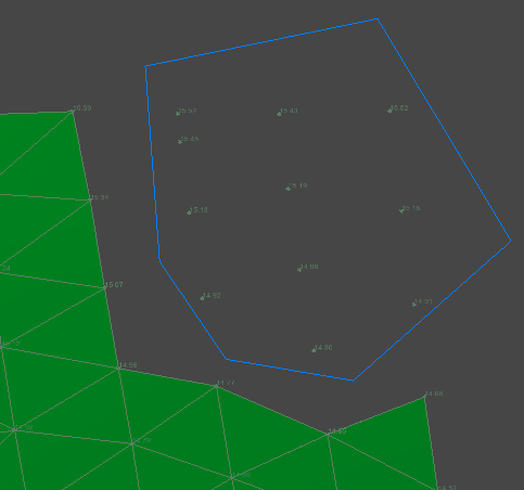
As well as manually snapping the end point back onto the start point you can right click and enable the Close Line option.
Delete a trim line from a surfaceThis tool allows you to remove a trim line you have already added.
After selecting the tool, the closest trim line highlights:
Click to remove the highlighted trim line:
By default the tool can select any trim line from any surface, but you can limit this to a specific surface using the right click menu Select Surface option. If a surface is selected this will be shown below the toolbar:

This option is for removing items from a specified region or removing everything except items within a region.
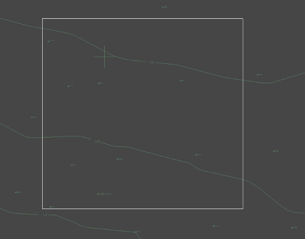
To delete items within a region or crop to a region, select the region by left clicking and dragging a rectangle over the desired area. Let go of the left mouse button when the region is where you want it. If you need to, you can respecify the rectangle by repeating the previous step.
Once you have a region specified, right click the mouse and choose either Crop To Selection or Remove Selection from the menu.
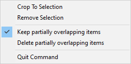
By default the "Keep partially overlapping items" option is ticked and Crop to Selection and Remove Selection behave as follows:
Switching to the "Delete partially overlapping items" option will additionally remove items that are only partially inside/outside the selected region. At least one point of a line must be inside the region for that line to be cosidered to be inside that region.
Note: The Crop To Selection function can be very useful if the 3D View display is looking less distinct than it usually does for other projects. This can be caused when an imported model has very large extents, thus causing the 3D View to reduce the level of detail for the relatively small region you are interested in. This display issue can be cured by using the Crop To Selection function to limit the drawing extents to only the region you need.