To see the list of drawing layers for the active project click the ![]() Layers toolbar button at any time.
Layers toolbar button at any time.
Also, most right-click menus in the drawing windows include a Layers option. 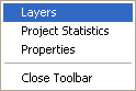
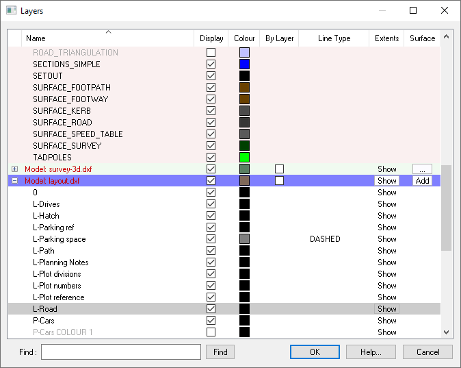
The Layers Window displays the layers for all the models in the active project. For example, one model may be a ground survey you loaded from a DXF file, and another may be an architect's indicative layout you've imported from another file.
Any design work you've done will be in the first model in the list. The different models are indicated by different background shades in the list, and the name of the model is shown in red text on a row preceding the list of layers for the model (known as the submodel header bar). The main design model is always at the top and has a light red background, the current ground survey model is shaded with a light green background and all other submodel layouts have a white background.
Layer information is shown under various column headers:
The first column contains the buttons which allow you toggle whether a model shows the layers associated with it. This allows you to collapse a model (-) and hide all the associated layers, or expand (+) a collapsed model and show all of its associated layers.
If you press the blank column header the layers will be ordered by their layer number. Additional clicks will toggle between ascending order and descending order.
The layers name is shown as was given in the original data file, or else as assigned by Site3D. To order the list by name, simply click the column header. Additional clicks will toggle between ascending order and descending order.
Each layer has a tick-box indicating whether it is currently displaying on the plan view window. You can click on the tick-box to change the display state of a layer. The plan view of the project will instantly update to show the difference of toggling the layer on or off.
A coloured box is shown for each layer. This indicates the colour for the items which are on that layer.
This colour is used when the ![]() Survey Colours toolbar button has been selected.
Survey Colours toolbar button has been selected.
You can click on the layer's colour-box to select a different colour for it.
There is a tick-box in the By Layer column for each model (not for the model's layers). When the By Layer box is ticked then the layers individual colours are used for drawing the items which are on it. When the By Layer box is not tick then the one colour in the Colour column is used for drawing all the layers (and the individual layers colours for the model are ignored).
By default each imported model is drawn in a grey colour, and this makes it easy to see which model is which on the plan view, and highlights the designed items which are in non-grey colours.
If the items on a layer are drawn with a particular line type then that will be indicated under this column.
The word Show appears under this column for each layer. If you click the mouse on the word Show then a rectangle will flash on the plan view indicating a bounding bound around all the items which appear on that layer, then the view will zoom to the highlighted extents. This can be very useful for finding a layer on the drawing.
Each layer has a tick-box indicating whether it is currently used in the 3D surface for the model. Initially, layers that are ticked under the Display column are also used for the 3D surface. You can click the tick-box under the Surface column to toggle layers on or off for the 3D surface. The effect is shown instantly on the 3D View window (and on the Plan View window if Survey Height Shading is in effect).
For example, your survey may include overhead power lines which are levelled higher than the ground surface. These lines would be undesirable in the 3D surface so you can untick their layer in the Surface column. However, you can still have the power lines displayed in the drawing by keeping the tick-box in the Display column.
To get to the Surface Properties Window click the surface properties button "..." which is under the Surface column on the right hand side of the header bar for each submodel that has a surface.
If the submodel in question doesn't have a surface yet, you can create one by clicking the "Add" button.
Typing into the find box will instantly start matching what you type against the layer names in the list.
This drop down allows you to quickly switch between layer states, doing this updates the current layer names, on or off states, and colours to match the setting of the selected layer state. See the following help page for more information on layer states and how they work: Custom Layer Names.
Each row in the list has a right-click menu which shows relevant options, depending on whether the row is a model name or layer, and what type of model it is. The following menu options will be shown for all items:
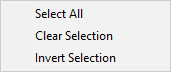
This option will highlight all the models and layers in the list. This can be very useful when you want to modify a property of all (or nearly all - de-select individual layers by holding the Ctrl key when clicking with the mouse). For example, you can select all layers and then click one of the Display boxes to turn them all on or off on one go.
The Clear Selection option de-selects all rows so that nothing is selected. It does not remove any model data, or make any other change.
The Invert Selection option is very useful for selecting all but one or two layers. For example, if you want to turn of everything except for one particular layer, then first select that layer, use the Invert Selection option, and then then click one of the Display boxes on a selected layer to turn them all off in one go.
In addition to the above right click menu options, the design models layers show the following options:

Selecting this option will bring up the Enter Layer Name window where you can specify a new name for the layer. The new name must be unique.
In addition to the above right click menu options, the design model or the current survey show the following options:
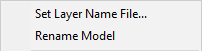
Clicking on this option will open a file selection window where you can pick the layer state configuration file to use as the default layer settings at the start of new projects. It will also apply its settings to this project and will be added to the layer state dropdown. See the following help page for more information on how to set up the default layer state file and how it works: Custom Layer Names/States.
The original project name/design model name is based on the initial file that the project was started from. Selecting this option will bring up the Enter Model Name window where you can specify a new name for the project.
In addition to the above right click menu options, models from imported drawings (models which are not the design model) show the following options:
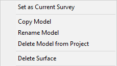
The Set As Current Survey option is offered for any model other than the model which is already set as the current survey model. Selecting this option will change which model is currently used as the main ground surface. The current survey surface will be shown by default in the 3D View window, and all design work is done relative to its levels.
Selecting this option will allow you to create a copy of the selected model, bringing up the Enter Model Name window. Clicking OK after entering the desired name for the copy will add it to the project.
Using the Copy Model option is an easy way to generate a topsoil strip surface model. After copying the survey, you can then use the Surface menu, Translate option on the copy to drop the surface by the topsoil strip depth (by entering the depth as a negative translation in the Z axis).
Selecting this option will bring up the Enter Model Name window where you can specify a new name for the selected model.
The Final Surface model and Formation Surface model created by Site3D cannot be renamed. However, the above Copy Model option can be used to create a copy with a new name.
Any model that is not the design model or the current survey may be deleted from the project. This can be useful for clearing out models that you once loaded into the project but now no longer require.
If you want to retain a model in the project but have it not shown in the drawing, then simply de-select the Display box on the model name row.
This option will allow you to delete the surface from the selected model. This will only remove the Site3D generated surface for the selected model and will not delete the model or any other elements within it.
In addition to the standard right click menu options, images have the following options:
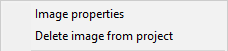
This option allows you to see the image properties and change the image drawing options. See Image Properties for more information.
The Delete image from project can be used to delete an image that you no longer require.