This option displays sets of cross-sections at regular intervals along a selected road.
On the ![]() centreline tools toolbar, click the
centreline tools toolbar, click the ![]() road cross-sections button.
road cross-sections button.
An options window is shown for the cross-sections:
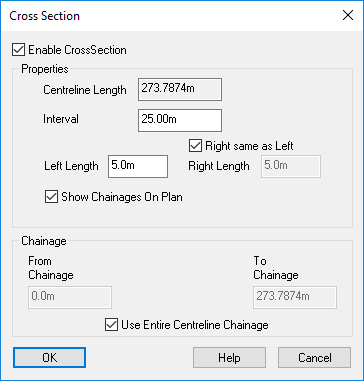
By default this checkbox is ticked, specifying that you are adding a new set of cross sections for the selected centreline. If you un-tick this box and click OK then it will instead remove any previously existing set of cross sections for the selected centreline.
Select the chainage interval at which you want each cross-section drawing to be generated.
This is the offset either side of the centreline over which each cross-section will extend. Normally, you will want the Left/Right Length to be at least the width from the centre of the road to the back of the footpath.
By default the left and right offsets are the same. If you want to specify one different to the other then deselect the "Right same as Left" checkbox.
This option will toggle whether the cross sections have their chainage value annotated in the plan view.
By default the first cross-section is taken across the start of the road (and the next one is at the specified interval along the road). However, you can specify the start chainage for the first cross-section so that it is not at the beginning of the road.
For example, if you specify the start chainage as 10m and the interval as 25m, then the first cross-section is generated at 10m along the road, the second at 35m, the third at 60m, and so on.
In order to specify a custom Start/End Chainage you will need to deselect the "Use Entire Centreline Chainage" checkbox.
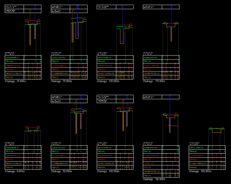
Click the OK button to see the Cross-sections View window, showing the fully annotated cross-section drawings.
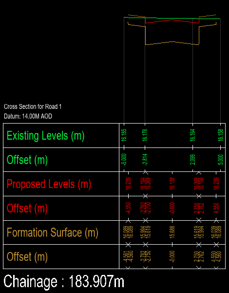
Below is an example of a single cross-section:
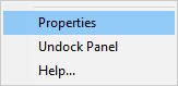
To configure the display of the cross-sections right-click the mouse to display a menu and select Properties.
The Cross-sections Properties window is shown:
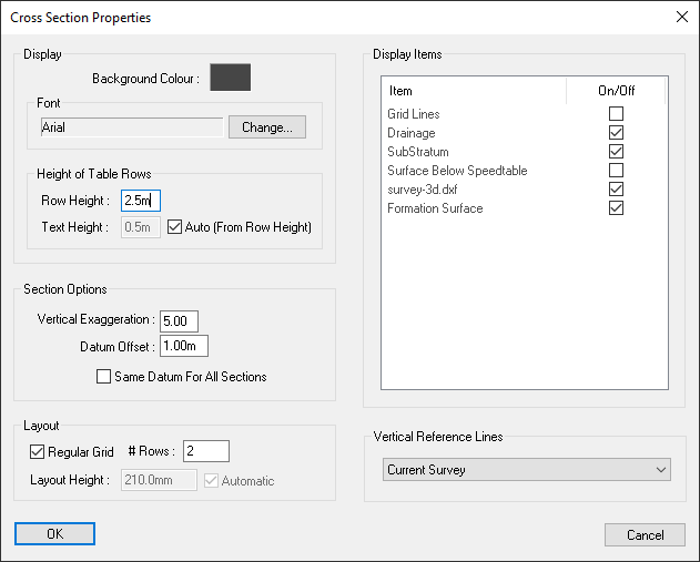
This specifies the height of the annotation boxes.
By default the text height is determined by the row height and the Auto box will be ticked. If you untick the auto box you can manually specify the text height.
Vertical Exaggeration allows you to set the scaling of the longsection along the vertical axis.
The datum of each section is automatically selected by Site3D according to the level range of the section drawing. The datum offset is then added below each automatic datum to provide additional spacing in the drawing.
If enabled the cross sections will all use the same datum, which is taken from the cross section with the lowest datum. This aligns the cross sections y axes, making it easy to compare level information across the different sections.
When regular grid is enabled, the cross sections will be positioned on a regular grid, having the same horizontal and vertical spacing between cross sections. # Rows specifies how many cross sections can be stacked vertically before being drawn in the next column.
When Regular Grid is disabled, the height of each cross section will vary depending on the number of annotation boxes and the level range of each section. Instead of having a set number of cross sections stacked vertically, the cross sections will stack as many as will fit within the specified layout height.
When Automatic layout height is enabled, the layout height will be selected based on the smallest sheet of standard sized paper that will fit all of the cross sections. A0 paper is the maximum automatic layout height that will be selected.
From this list you can toggle which section items are drawn. The drawing will be updated and show any changes immediately.
You can select which surfaces will have vertical references lines applied at the points where there is a change in the surface.