To access the tools for adding and modifying drainage click the ![]() button, or select the Add/Edit Drainage Run... option on the Drainage menu.
button, or select the Add/Edit Drainage Run... option on the Drainage menu.
You will see this toolbar appear on the top left of the plan view window:


![]() Work on Storm Sewer Drainage
Work on Storm Sewer Drainage
![]() Work on Foul Sewer Drainage
Work on Foul Sewer Drainage
You must select either to work on ![]() Storm Drainage, or
Storm Drainage, or ![]() Foul Drainage.
Whichever button is selected determines whether the rest of the buttons on the toolbar will operate on the Storm water drainage network, or the Foul water drainage network.
Foul Drainage.
Whichever button is selected determines whether the rest of the buttons on the toolbar will operate on the Storm water drainage network, or the Foul water drainage network.
![]() Start, or Add to, a Drainage Run
Start, or Add to, a Drainage Run
![]() Add Manhole into a Conduit
Add Manhole into a Conduit
![]() Move a Manhole
Move a Manhole
![]() Delete a Manhole
Delete a Manhole
![]() Delete a Conduit
Delete a Conduit
![]() Edit Manhole Properties
Edit Manhole Properties
![]() Edit Conduit Properties
Edit Conduit Properties
![]() Set the Gradient along a Drain Run
Set the Gradient along a Drain Run
![]() Set Pipe Diameter along a Drain Run
Set Pipe Diameter along a Drain Run
![]() View Long-section along Drain Run
View Long-section along Drain Run
![]() Create a Schedule of the Manholes
Create a Schedule of the Manholes
![]() Create a Schedule of the Drainage Connections
Create a Schedule of the Drainage Connections
![]() Turn gullies On/Off
Turn gullies On/Off
![]() Move Drainage Annotation
Move Drainage Annotation
![]() Rotate Drainage Annotation
Rotate Drainage Annotation
![]() Delete Network
Delete Network
![]() Modify Drainage Display Properties
Modify Drainage Display Properties
![]() Open the manhole properties schedule for a drainage network
Open the manhole properties schedule for a drainage network
![]() Open the conduit properties schedule for a drainage network
Open the conduit properties schedule for a drainage network
![]() Click this button to close the toolbar
Click this button to close the toolbar
Site3D performs automatic clash detection after every change to the drainage network. If two pipes clash, or pass close to each other, a design alert will show on the drawing highlighting where there this occurs. The design alert window has more information, such as which two pipes are crossing, the coordinate of the clash, and clearance distance if not a physical clash.
For more information on clash detection and design alerts, see the Design Alerts help page.
Generally, the invert levels of conduits will match the invert level of the manhole and Site3D will try to maintain this when using the drainage tools. For example, in the longsection view if you use the move manhole tool, the invert levels of the pipes at that manhole will be updated to match the new invert level of the manhole.
However, it is possible to design a backdrop if there are two or more pipes connected to a manhole. This can be done by using the ![]() Conduit Properties tools to select the pipe that you want to backfall into the manhole, then setting the soffit or invert levels of a pipe.
Conduit Properties tools to select the pipe that you want to backfall into the manhole, then setting the soffit or invert levels of a pipe.

To create a new drainage run click the ![]() button.
button.
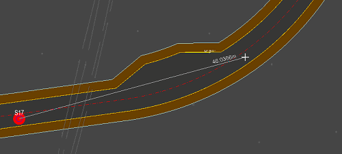
Click the position for the first manhole. As you move the mouse to place the next manhole, you will see a line stretching to the cursor position, representing the conduit between the two manholes. Click to place the next manhole, and so on. When you are finished, right-click the mouse and select Quit Command from the menu, or press the Escape key on the keyboard.
If you click on, or very close to, another manhole of the same network type (Storm or Foul), a new manhole is not placed, but instead the new conduit joins into that manhole. Thus it is easy to join runs to make a drainage network.
Similarly, if you click on, or very close to, another conduit of the same network type (Storm or Foul), a new manhole is inserted into the selected conduit joining to the new conduit you are adding.
Note: By default, each new manhole is placed at a depth such that the conduits which join into it have a soffit level of 1.2m below cover level. The pipes join soffit to soffit through the manhole.
By default, all drainage is added as adoptable. You can switch to adding new drainage as Private/Plot Drainage from the Drainage menu or, if the new drainage tool is active, from the right-click menu.
Clicking the Private/Plot Drainage menu option will toggle between adding new manholes as private or as adoptable drainage. A tick is drawn next to the option if you are currently in Private/Plot Drainage mode.
From the right-click menu (while adding new drainage):
You can also change this from the Drainage menu:

Manholes placed while in Private/Plot Drainage mode will be added using the default manhole properties for private/plot drainage.
This can be toggled from the right click menu when the add new drainage tool is active:
To create pipe to pipe junctions when creating a new drainage run, tick on the Drainage -> Private/Plot Drainage menu item. Then start or end a pipe run on or very near a conduit of the same network type (Storm or Foul) and it will automatically connect the pipes together with a junction, making it easy to join runs together midway into another conduit.
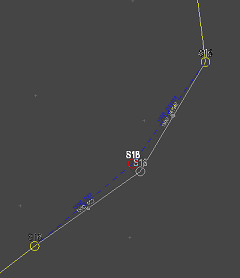
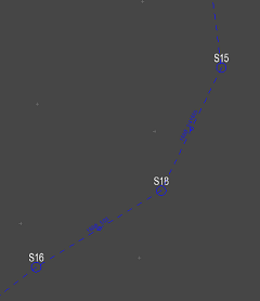
To add a new manhole into a conduit, click the ![]() button.
button.
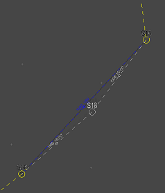
Select the conduit into which the manhole is to be added. When you click the mouse, a new manhole appears at the cursor position, showing how it will join into the network. Move the mouse to the required position for the new manhole and click to place it.


Note: By default, each new manhole is placed at a depth such that the conduits which join into it have a soffit level of 1.2m below cover level. The pipes join soffit to soffit through the manhole.
Note: If a manhole is shown in a bright red disc (as for S15 in the above example), it indicates that it will not fully drain (i.e. it is lower than all its joining conduits)
To move a manhole, click the ![]() button.
button.
Select the manhole by clicking near it with the mouse. When selected, the manhole moves with the cursor. Move the cursor to the new position and click to place the manhole.
Note: When a manhole is moved, its cover level will change to that of the new position, but its invert level will remain as before. Therefore the depth of the manhole will change. Similarly, the invert level of the joining conduits will remain the same, but their length will alter, and so gradient of the conduits will change accordingly.
Note: If the moved manhole was a junction connection, the invert level is also adjusted to keep the junction connection soffit to soffit. Site3D will also restrict the movement to avoid bending the joined-onto pipe.
To delete a manhole, click the ![]() button.
button.
Select the manhole by clicking near it with the mouse. The selected manhole will be removed along with all conduits which joined into it.
Note: You can reverse the deletion by using the Undo facility straight after.
To delete a conduit, click the ![]() button.
button.
Select the conduit by clicking near it with the mouse. The selected conduit will be removed from the network, breaking the connection between the manholes at either end.
Note: You can reverse the deletion by using the Undo facility straight after.
To create or move a schedule of the manholes, click the ![]() button.
button.
An outline box is shown next to the cursor, indicating the size of the manhole schedule table. Move the cursor to where you want to place the schedule on the drawing. Click to place it.
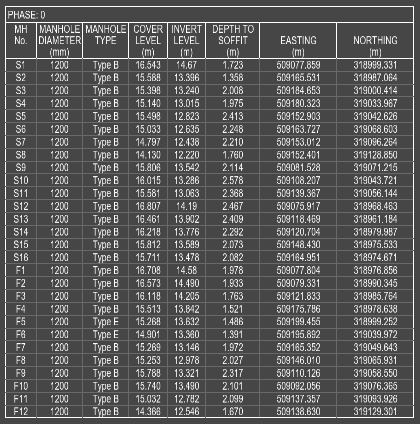
The manhole schedule displays current information about the drainage network. If you change the drainage network then the manhole schedule will automatically update to show the correct information.
If you want to reposition the schedule on the drawing, click the ![]() button, and redo the placement of the schedule box.
The existing schedule will move to the new position.
button, and redo the placement of the schedule box.
The existing schedule will move to the new position.
You can modify the manhole schedule properties by using the Drainage->Manhole Schedule Properties menu option:

If the Grouped Ascending or Grouped Descending sorting style is set, the manhole schedule will be split into multiple tables with each network group being a separate table.
When Separate Phases is enabled, the manhole schedule will be split into multiple tables with each phase being a separate table.
When Include Private is enabled, the private/plot drainage will be included in separate tables.
You can toggle on and off columns to suit the information you need. Below is information on columns that are toggled off by default.
Diagram
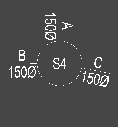
Show a small top-view diagram of each manhole, this combines the information from the Drainage Schedule into the Manhole Schedule.
Conduit Invert Levels
Display all the connected conduit invert levels
Base Level Column
The Base Level column shows the level at the bottom of the catchpit for manholes that have a catchpit depth.
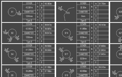
The drainage schedule shows a small top-view diagram of each manhole, indicating the position and size of each incoming connection.
To create or move a drainage schedule , click the ![]() button.
button.
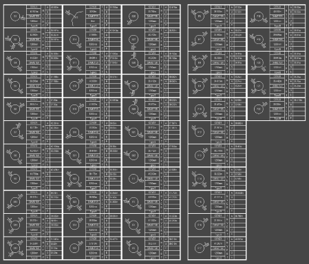
The grids of manhole diagrams are paged out to make it easy to print the schedule on standard paper sizes.
Road gully positions are calculated automatically, according to the drainage area set in the road properties.
This toolbar button toggles the display of the gullies.
Note: You can also turn the gullies on/off using the layers window.
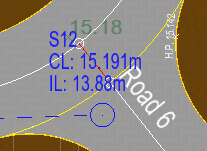
After creating a manhole or conduit, the annotation is automatically placed on the plan. The automatic placement of manhole annotations looks at the other annotations in the same drainage network and determines a location that does not overlap other texts. This will also be recalculated after any design change. While this often does a good job at placing the text the text may still overlap other design items on the site or texts on imported drawings.
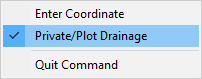
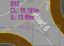
If you click the Move Drainage Annotation button you will highlight the nearest manhole or conduit annotation text. If you click with an annotation selected you will see a box indicating the new textbox location and a line going from the manhole/conduit to the centre of the box:
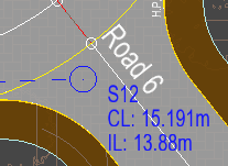
If you click again the textbox will be manually positioned to the indicated location:
To finish right click and select Quit Command from the right-click menu.
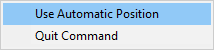
To revert back to automatic positioning you can use the Move Drainage Annotation tool to select an annotation, then right click and select Use Automatic Position, this will revert the selected annotation back to automatic positioning. Alternatively, you can enter the Move Annotation tool and right click without having an annotation selected. Then, from the right click menu, select Use Automatic Position. This will allow you to select multiple annotations in a row to set them back to automatic positioning. When you are done you can right click again and untick Use Automatic Position to return to manual text position or select Quit Command.
The rotate annotation option works the same way as the move annotation tool but instead allows you to override the default rotation. Again, you can right click and select Use Automatic Position to reset the annotation position and rotation if desired.
This option will delete the closest drainage network including its drainable areas. If you want to delete a sub-section of the network you can first use the Delete Manhole tool to separate the section from the rest of the network, and then use this option on the disconnected section.
This toolbar button brings up the Drainage Properties window, here you can specify how the manholes and conduits are annotated.
You should see the following window:
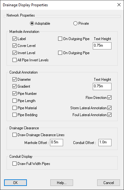
For more information see the Drainage Properties window help page.
For more information see the Manhole Properties Schedule help page.
For more information see the Pipe Properties Schedule help page.