This option generates a longsection view of the drainage network along a run of conduits between two manholes.
On the ![]() drainage tools toolbar, click the
drainage tools toolbar, click the ![]() drainage longsection button.
drainage longsection button.
You then select the two manholes between which the longsection should be generated:
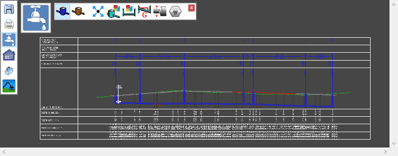
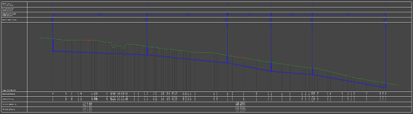
The longsection view window is shown with a fully annotated drainage long-section drawing:
The toolbar on the longsection window has the following buttons:
![]() Move a Manhole
Move a Manhole
![]() Edit Manhole Properties
Edit Manhole Properties
![]() Edit Conduit Properties
Edit Conduit Properties
![]() Set the Gradient along a Drain Run
Set the Gradient along a Drain Run
![]() Set Pipe Diameter along a Drain Run
Set Pipe Diameter along a Drain Run
![]() Toggle drainage items On/Off
Toggle drainage items On/Off
![]() Click this button to close the toolbar
Click this button to close the toolbar
To move a manhole, click the ![]() button.
button.
You can select one of the manholes on the longsection drawing and move it up/down. The manhole's joining conduits also move up/down with it.
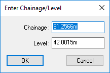
You can also right-click to see a menu for further options, you can select Enter Level for exact positioning.
To set the gradient on a conduit, or a run of conduits, click the ![]() button.
button.
You should now select the two manholes between which the gradient is to be set. They can be adjacent manholes for setting a single conduit gradient, or they can be separated by a run of conduits and manholes.
You will be prompted to select the start manhole position from the drawing.
As you move the mouse cursor the nearest manhole is highlighted.
Click to select.
Then you will be prompted to select the end manhole for the run.
As you move the mouse cursor the nearest manhole is highlighted.
Click to select.
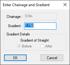
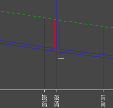
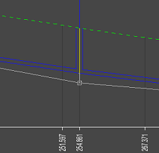
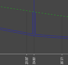
The following images show the difference after setting the whole run to a gradient of 1:50 (2%).
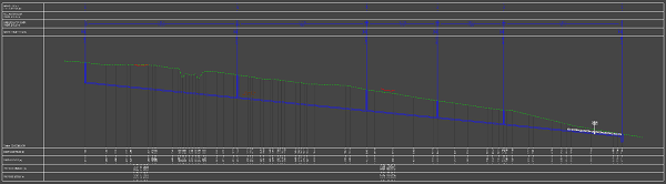
Note: The gradient is set from the first selected manhole, which will maintain its depth. The depths of all the other manholes in the selected run are adjusted to achieve the specified conduit gradient.
To set the diameter of a conduit, or a run of conduits, click the ![]() button.
button.
You should now select the two manholes between which the conduit diameter is to be set. They can be adjacent manholes for setting a single conduit diameter, or they can be separated by a run of conduits and manholes.
You will be prompted to select the start manhole position from the drawing.
As you move the mouse cursor the nearest manhole is highlighted.
Click to select.
Then you will be prompted to select the end manhole for the run.
As you move the mouse cursor the nearest manhole is highlighted.
Click to select.
You will be prompted to enter the required diameter for the selected conduits.
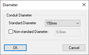
Either select a standard diameter from the drop-down list, or select the Non-standard Diameter option and enter your desired diameter.
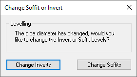
When the conduit diameter changes, either the soffit levels can adjust, leaving the invert levels unchanged, or the invert levels can adjust, leaving the soffit levels unchanged. You are prompted to choose which is appropriate for the current diameter change.
To change which drainage items are displayed on the longsection drawing click the ![]() button.
button.
You will be prompted to select a manhole from the drawing.
Note: Any manholes which are currently Off are shown drawn in grey so that they may be selected for change.
As you move the mouse cursor the nearest manhole is highlighted. Click to select.
You will be prompted for the display option for the selected manhole.
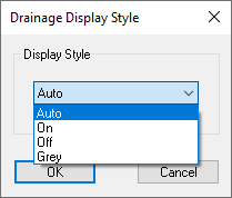
The default display style for all manholes is Auto, which means the software will display all reasonable drainage items.
A display style of On will force the particular manhole to be displayed regardless. This is sometimes useful where the auto rules would otherwise cause the manhole to be left off.
A display style of Off will force the particular manhole to not be shown on the longsection drawing. This can sometimes be useful where two manholes, or their joining conduits, overlay each other on the drawing.
Note: An Off manhole is shown in grey while the toggle operation is still active (so that they can still be seen for selection). When the toggle operation is finished then Off items will then not be visible.
A display style of Grey causes the manhole, and its joining conduits, to be drawn in grey instead of the usual blue (for storm sewer) or brown (for foul sewer). This can be useful where a manhole is not important for the purpose of the particular drawing, but it is important that the manhole is shown in position.