To access the options for the drainage annotation, from the ![]() drainage tools toolbar, click the
drainage tools toolbar, click the ![]() Drainage Display Properties button.
Drainage Display Properties button.
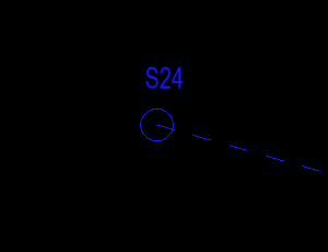
This window appears:
At the top of the window there are two radio buttons, Adoptable and Private. The currently selected option will determine whether you are editing the display properties of adoptable networks or the display properties for private networks. Toggling between adoptable and private will store the changes you have made to any properties, so when you toggle back you will see your previous changes.
Clicking OK will update both the adoptable and private properties of the project. Clicking Cancel will discard any changes.
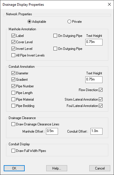
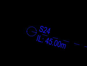
This option enables display of the manhole name on the plan-view drawing.
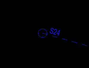
If On Outgoing Pipe is ticked then the label will instead be drawn along the outgoing pipe.
This option enables display of the manhole diameter on the plan-view drawing.
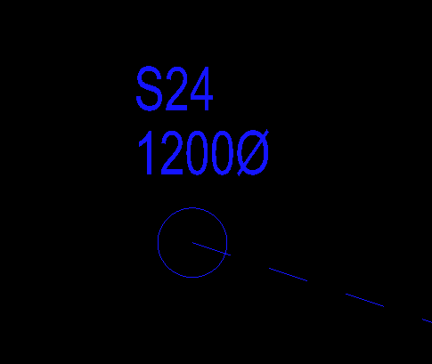
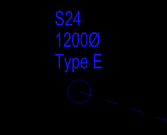
This option enables display of the manhole type on the plan-view drawing.
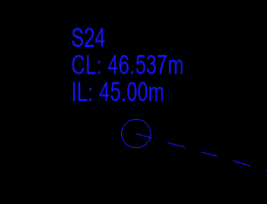
This option enables display of the manhole cover level on the plan-view drawing.
This option enables display of the manhole invert level on the plan-view drawing.
If On Outgoing Pipe is ticked then the label will instead be drawn along the outgoing pipe.
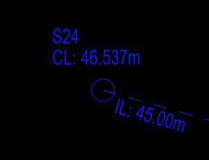
With On Outgoing Pipe enabled for both the manhole label and invert level, the annotations are drawn along opposite sides of the outgoing pipe:
This text box allows you to specify the size of the manhole annotation text displayed on the plan-view drawing.
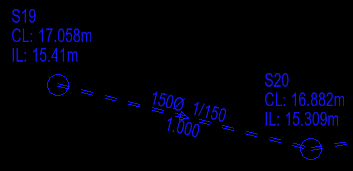
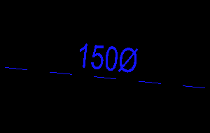
This option enables the display of the conduit internal dimensions on the plan-view drawing. This is positioned above the pipe line, half way along.
This option enables the annotation of the conduit gradient on the plan-view drawing. This is positioned above the pipe line, half way along.

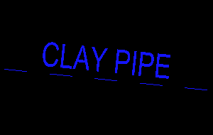
This option enables the annotation of the conduit material on the plan-view drawing. This is positioned above the pipe line, half way along.
The material of a conduit can be specified in the conduit properties.
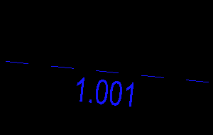
This option enables the annotation of the conduit pipe number (for example, 1.001). This is positioned below the pipe line, half way along.
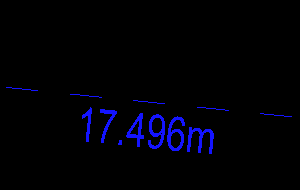
This option enables the annotation of the conduit length. This is positioned below the pipe line, half way along.
This option enables the annotation of the conduit bedding type. This is positioned below the pipe line, half way along.
The bedding type of a conduit can be specified in the conduit properties.

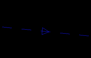
This option enables the direction of flow annotation arrow on the plan-view drawing. This is positioned half way along the pipe line.
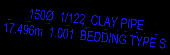
Here is an example showing the order of pipe annotations when all annotations are turned ON at the same time:
These options enable or disable the above drainage annotations for lateral connections (a pipe connected to a manhole which is flagged as a lateral - See Manhole Properties).
This text box allows you to specify the size of the conduit annotation text displayed on the plan-view drawing.
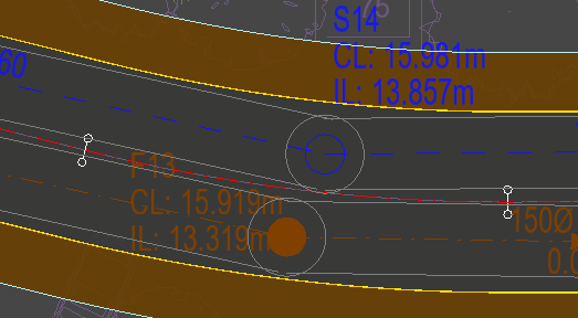
When Draw Drainage Clearance Lines is enabled, guide lines will be drawn at the specified offsets from the outer edge of the drainage.
Note: The checkbox to toggle the drawing of these lines affects both private and adoptable drainage, this is because this option sets the visibility state of the DRAIANGE_KERB_CLEARANCE layer.
For example, this allows you to visually verify that the drainage is further than the required minimum offset from the kerb. The default values are based on the Design and Construction Guidance of highway sewers, which states that outer edge of pipes should be at least 1m from the kerbline and manholes 0.5m from the kerbline.
When Draw Full Width Pipes is ticked the conduits will be drawn on the plan view as two parallel lines at the width of the pipe diameter.
Below is an example of the pipes drawn at full width: