Unfilleted IP
 Unfilleted Curve IP
 Superfluous IP
 Superfluous Curve IP
 Level Jump
 Horizontal Channel Kink
 Roundabout ICD Dead Area
 Physical Pipe Clash
 Near Pipe Clash
 Pipes Clash at Manhole
 Undersized Manhole
Site3D performs various design checks in the background as you make modifications. When a design issue is detected, Site3D will highlight this to the user in the form of a design alert symbol on the drawing.
Unfilleted IP
Unfilleted Curve IP
Superfluous IP
Superfluous Curve IP
Level Jump
Horizontal Channel Kink
Roundabout ICD Dead Area
Physical Pipe Clash
Near Pipe Clash
Pipes Clash at Manhole
Undersized Manhole
To hide or show the current set of design alert symbols on the drawing, toggle the ![]() Hide/Show Design Alerts toolbar button.
Hide/Show Design Alerts toolbar button.
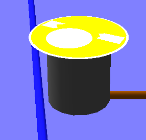
To see the information about a particular design alert, simply click the mouse on it in the Plan View when no command is active, the highlighted alert will open.

Example design alert in plan

Example highlighted design alert in plan
To see the list of current design alerts, click the ![]() Review all Design Alerts toolbar button:
Review all Design Alerts toolbar button:
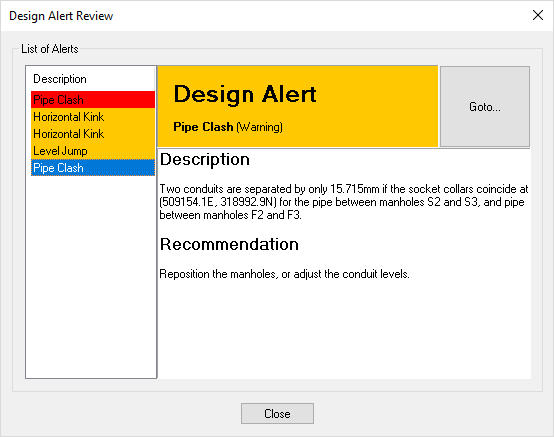
Example list of design alerts with pipe clash description
To see the details of a specific design alert, click on the design alert name in the list on the left hand side and more details about this design alert will show in the description on the right hand side.
Click the Goto... button to display the location of the particular design alert in the Plan View.
The different types of design alerts are described below.
Unfilleted IPAn Unfilleted IP design alert indicates that there is a sudden change in the direction of the centreline at the IP (Intersection Point).
This is undesirable because:
This design alert can be resolved by adding a fillet radius to the IP.
Non-Tangential CurveAn Non-Tangential Curve design alert indicates that there is a sudden change in the direction of the centreline at the end of a curve.
This is undesirable for the same reasons as the Unfilleted IP and also:
This design alert can be resolved by removing the IP from the end of the curve.
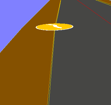
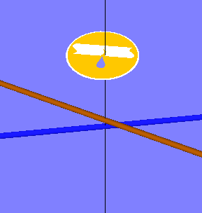
Superfluous IPA Superfluous IP design alert indicates that the highlighted IP is not needed as it is collinear, meaning that it lies on the line connecting the IPs on either side. In other words, it has no affect on the centreline horizontal alignment.
It is undesirable to have superfluous IPs because:
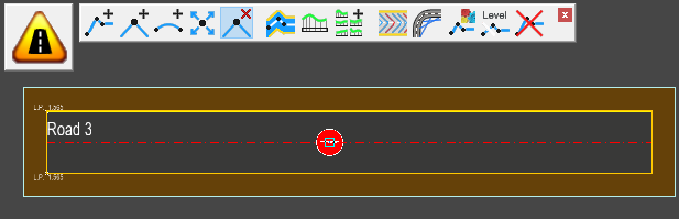
In this image, the IP with the design alert is being hovered over whilst the the delete point tool is active.
When the delete point tool is active it shows how the centreline will change if used, in this case there is no difference to the centreline design, thus verifying that the IP point is superfluous.
This highlights that the IP point can be safely deleted without affecting the centreline design.
To resolve this design alert you should remove the IP that is flagged by the design alert.
Superfluous IP at Curve TangentA Superfluous IP at Curve Tangent design alert indicates that the highlighted IP is on a tangent point.
A superfluous curve IP can cause levelling issues with the centreline channels, kerbs or footways and may negatively impact your design.
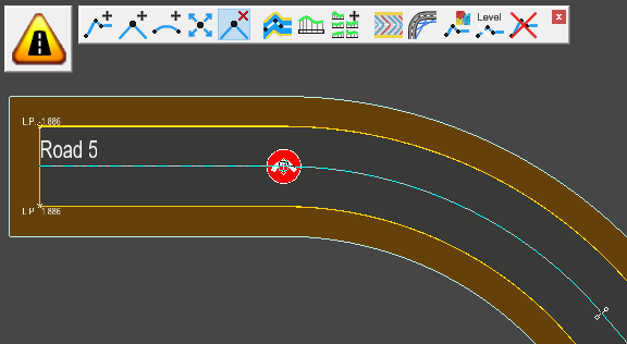
In this image, the IP with the design alert is being hovered over whilst the the delete point tool is active.
When the delete point tool is active it shows how the centreline will change if used, in this case there is no difference to the centreline design, verifying the IP point is superfluous.
This highlights the fact that the IP point can be safely deleted without affecting the centreline design.
To resolve this design alert you should remove the IP that is flagged by the design alert.
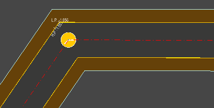
Level JumpA level jump design alert is shown wherever there is a significant change in road channel level over a very short distance. The design alerts indicates that Site3D has automatically smoothed the channel levels in this area in order to reduce the suddenness of the level change, and therefore the crossfall/camber may not be as intended in this region.
For example, in the image below, channel point 'B' is levelled from centreline point 'A' and channel point 'C' is levelled from centreline point 'D'. If the centreline levels raise or drop dramatically over the centreline distance 'A' to 'D' then the levels on the channel have to change by a similar amount but over the much shorter channel distance 'B' to 'C'.
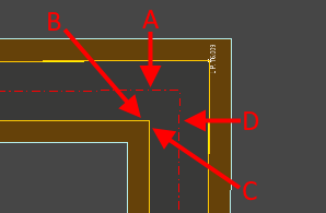
Sharp horizontal bend with no corner radius.
In this example, the design alert shows where the channel levels have been smoothed out.
Note: The back-of-footway still shows the sudden level drop, as only the channel levels are automatically smoothed.
You can resolve this design alert by increasing the centreline corner radius so that the corner radius is significantly larger than the distance from centreline to inside channel.
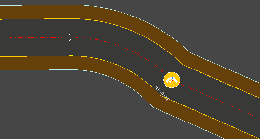
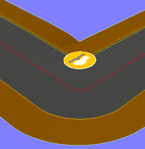
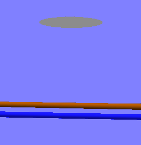
Horizontal KinkA horizontal kink design alert indicates where a road's channel has resulted in a slight but sudden change in direction. The kink may be as a result of an unfilleted centreline IP or an IP filleted with a small arc, or the particular road geometry resulting in a small reverse curve on the channel.
The kink is highlighted because the road may appear straight on the plan drawing, but when viewed from driver's eye height at ground level it would appear as a kink due to the 'foreshortening' effect when looking along the road. This can usually be seen in the 3D View, as with the following example:

When viewed from above the channel looks straight.
When viewed in 3D from driver's eye height, the kink is clearly visible.
To resolve the design alert, review the centreline geometry which has resulting in the channel kink. For example, you may need to increase the curve radius of a centreline IP, or remove an unintended IP from the end of a centreline arc (which is preventing the centreline from being tangential).
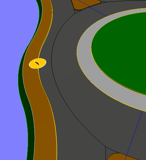
Roundabout ICD Dead AreaA Roundabout ICD Dead Area design alert indicates when it was not geometrically possible to remove the dead area between two sequential arms. This may happen if a roundabout arm is too close to another for their specified entry/exit radii to fillet, or if the arms are too far apart.
A dead area is a region of the road surface which most cars will never driver on. Stones and debris will build up on the dead area, which can present a hazard for those vehicles that do occasionally drive on it, especially motorcyclists.
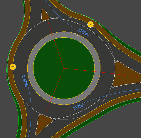
In this example, two of the three dead areas cannot be removed (or straightened) because there is no geometric solution to achieve all the specified curve radii.
In the 3D View you can see the reverse curve when driving straight from entry to exit, giving a region of road surface on which most cars won't drive.
You can resolve this design alert by either moving the two roundabout arms, modifying the fillet radii, or by forcing OFF dead area removal on the entry arm.
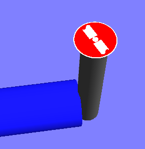
Physical Pipe ClashA red Pipe Clash design alert indicates when two pipes physically intersect one another. The physical intersection detection takes account of the pipe wall thickness and collar diameter of the particular conduit types, i.e. worst case scenario if the pipes should coincide collar to collar.
Pipes in 3D view shown to be intersecting.
You can resolve this design alert by either moving the manholes so the pipes no longer cross horizontally, or adjust the invert levels of the manholes so one pipe crosses above or below the other with a reasonable clearance.
Near Pipe ClashAn amber Pipe Clash design alert indicates when two pipes come within 200mm of each other but don't actually physically intersect. The distance between crossing pipes is calculated from the outer edge of both pipes, taking account of the pipe wall thickness and collar diameter of the particular conduit types, i.e. worst case scenario if the pipes should coincide collar to collar.
Pipes in 3D view shown from the side not to be actually colliding, but very close.
You can resolve this design alert by either moving the manholes so the pipes no longer cross horizontally, or adjust the invert levels of the manholes so one pipe crosses above or below the other with a reasonable clearance.
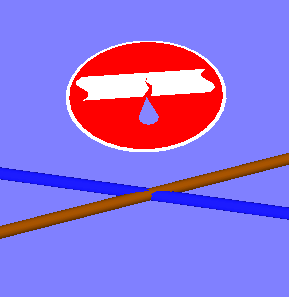
Pipes Clash at ManholeA blue Pipe Clash design alert indicates when two pipes enter a manhole too close to each other, such that it may be physically impossible to construct the connections into the manhole on site.

The two pipes entering on the left of this manhole are too close to each other.
You can resolve this design alert by either increasing the manhole diameter, or moving the other end of one pipe that they enter the manhole at a less acute angle.
Note: The clash detection is done on the basis that both pipe connections are to the centre of the manhole. In practice it may be possible to physically align the pipes side-by-side, offset from the centre.
Undersized ManholeAn Undersized Manhole design alert indicates when an incoming or outgoing pipe is too large to ensure sufficient internal benching.
Pipe in 3D view is too large for the manhole.
To resolve undersized manhole design alerts, simply increase the manhole diameter or decrease the pipes that enter or leave this manhole.
 Physical Manhole Clash
A red Manhole Clash design alert indicates when a manhole or a pipe physically intersect another manhole. The physical intersection detection takes account of the external diameter of the two conflicting items, i.e. worst case scenario if the pipe collar should coincide at the manhole.

 Near Manhole Clash
An amber Manhole Clash design alert indicates when a manhole or a pipe comes within 200mm of each other but don't actually physically intersect another manhole. The distance between the two entities is calculated from the outer edge of both items taking account of the pipe wall thickness, collar diameter and manhole wall thickness, i.e. worst case scenario if the manhole should coincide at the pipe collar.