This option has settings for the general properties of a road.
On the ![]() centreline tools toolbar, click the
centreline tools toolbar, click the ![]() road properties button.
road properties button.
You will be prompted to select a road from the drawing. As you move the mouse cursor the nearest road centreline is highlighted. Click to select. The road properties window is shown.
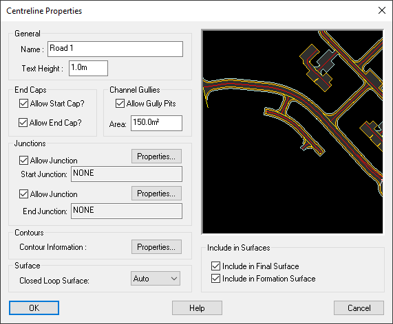
The road name is shown, and you can change it to whatever you like (for example, "High Street"). The default name is "Road X", where X is a sequential number for each new road. The road name is displayed on the drawing near the road start position.
This is the text height for the centreline name in model units. Setting this value to zero hides the road name, and any value greater than zero is used as the text size.
By default a road will be capped at its start and end (if there is no junction or roundabout there). This means that the channel, kerb and footpath are constructed to cap-off the road.
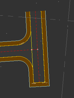
To illustrate, this example of a small turning road shows a cap on the southern end, and no cap on the northern end.
You can use the Allow Start Cap and Allow End Cap options to determine the capping behaviour for the particular road.
The Allow Junction tick boxes determine whether Site3D will automatically offer the create junctions at the start/end of the road whenever one would be appropriate (i.e. when it comes close to another road).
If the start/end is already junctioned then the name of the road onto which it is junctioned is shown. Clicking the Properties button will show the Junction Properties window for that junction.
By unticking the Allow Junction option you can force the removal of a junction, and also Site3D won't offer to subsequently re-create a junction for this road end.
By default, Site3D will automatically calculate the optimum positions for drainage gullies on the road. The gullies can be seen on the drawing when the GULLIES layer is set on in the layers window.
The number and position of gullies is dependent on the surface area of road which is required to be drained by each gully. That surface area is shown here and can be changed if you have a particular requirement for this road.
If you do not want gullies on a particular road then untick the Allow Gullies box.
By default, contour properties for each road are controlled by the Contours option on the Road Tools toolbar. If you want to set specific contouring properties for this road then you can do so by clicking the Properties button.
The Closed Loop Surface option allows you to set centreline to create a surface when the centreline is joined start-to-end. The design surface can then be levelled by setting the centreline vertical alignment.
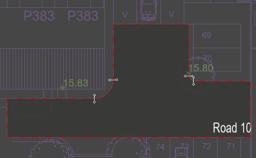
A centreline with Closed Loop Surface option set on.
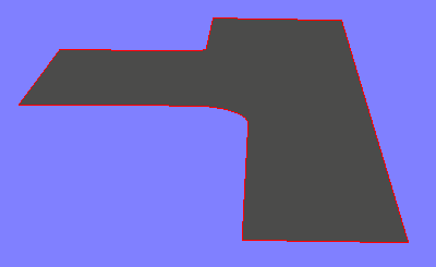
The surface shown in the 3D view.
The Include in Final Surface and Include in Formation Surface options allows you to set whether or not this road will be included when creating the Final surface or Formation Surface.
Every road and path is initially set to be included in the final and formation surfaces that are created in Site3D. These tick boxes allow you to disable this to exclude a specific road/path from the final surface, or formation surface, or both.