To output the results from Site3D use the File->Save As... menu option.
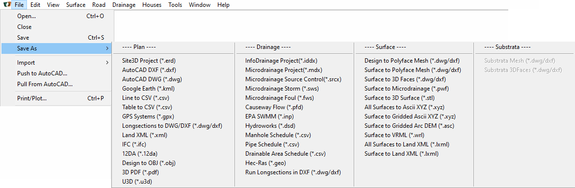
The menu is categorised into four types of output file, as follows:
This is the file format used natively to store all details and data of the drawing and design model. When an ERD file is re-opened it will show the project exactly as it was when you saved it.
The DXF file format can be read by most other CAD related software applications. This is the Autodesk published format for drawing exchange.
When you select this option you will get a preview window with a few optional settings.
Site3D will save in the 2004 version of DXF unless the particular entities being saved require the 2007 version or the 2010 version.
To export DWG format files it is necessary to have the free DWG/DXF Converter application installed. It can be found on the Open Design Alliance website:
https://www.opendesign.com/guestfiles/oda_file_converter
If you have not yet installed the converter, you will be prompted to do so when you try to import/export a DWG. It will offer to show you the web-page where the converter can be downloaded for install.
After installing the converter, DWG export and import will operate seamlessly. The converter's icon may display on the Windows taskbar during the DWG import and export operations.
When you select to save as DWG you will get a preview window with a few optional settings.
Site3D will save in the 2004 version of DWG unless the particular entities being saved require the 2007 version or the 2010 version.
You can export the drawing in KML format, so that your design will display in-situ in Google Earth.
After selecting the folder and file name for the KML file, you will be prompted with the following option:
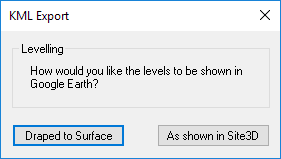
The default is to drape the design onto the Google Earth ground surface. The alternative is for Google Earth to show the design items at the 3D levels according to your design. In most cases it is best to drape the model because the Google Earth ground surface is likely to be less accurate than your ground survey model, and as such, much of your 3D design might be just underneath the Google Earth ground surface, and hence not visible in Google Earth. Selecting the drape option ensures your design will be visible when viewed in Google Earth.
When you open the *.kml file with Google Earth it will zoom into the location which matches the coordinates of your drawing.
This is very useful for visualising exactly where a survey drawing is situated within the UK.
The gloabl position (latitude and longitude) will be correct if you are working to a known coordinate system, for example, UK Ordnance Survey or US State Plane. (See Project Options)
This is a facility for exporting design line coordinate data in CSV format, representing one of the designed features (for example, a road centreline, or a channel line). The format is suitable for reading directly into setting-out devices on site.
When this output option is selected you will be prompted to choose a design line from the drawing and then a chainage interval at which points (X,Y,Z) will be written to the CSV file.
This is a facility for exporting a setting-out table to CSV files (for example, centreline setting-out). The format is suitable for reading directly into the setting-out devices on site.
When this output option is selected you will be prompted to choose a setting-out table from the drawing, which is to be written to the CSV file. This facility is similar to Line to CSV except that it exports additional information from the table, such as tangent points and point type.
This file format is compatible with popular GPS devices, and can also be loaded by Google Earth. The output GPX file will contain only the designed road lines.
This option produces a DXF file containing the longsection drawings from all of the roads in the design. The longsections are displayed one below the other in the DXF drawing. Each one is drawn up as it would be shown in the vertical alignment view for the road.
This is a facility to export design information to Land XML files. After clicking this option, simply choose the filename for it to be saved as. Currently supported export features: road centrelines, drainage manholes and drainage conduits.
This option produces an IFC 2x3 file containing 3D design surface information and solid 3D drainage items with attributes ready to import into your BIM package of choice.
Click here for further details.
This facility is for exporting design alignment information to 12DA format. Currently supported export features: road centrelines.
This facility is for exporting to OBJ format and is useful for creating virtual environments. Currently supported export features: final surface (roads, footways and earthworks) and house walls and slabs.
Click here for further details.This facility is for exporting 3D PDFs of the site. Note 3D PDFs are not widely supported by PDF readers. Currently supported export features: roads and final surface.
This facility is for exporting to U3D format. Currently supported export features: survey surfaces, final surface (roads, footways and earthworks).
This is the recommended format for transferring drainage networks to and from InfoDrainageTM. This is useful where you want to use InfoDrainage to design your pipe sizes and invert levels, and to simulate the system under various storm conditions.
After clicking this option you will be shown a list of potential drainage networks in your design that you can choose to select to export.
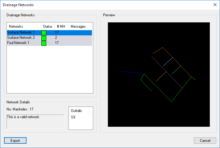
Next to each network will be a status colour. Green means it will export, whereas red means something needs your attention. If the status colour is red please look at the status message below the list of networks. Select a network from the list and the status message will inform you of anything that needs your attention to enable this network to export. For example, each network must have an outfall specified.
Ponds will be included in the InfoDrainage project with the drainage network if relevant. For more information on pond export see the Pond Export help page.
NOTE: You can select multiple networks for export into the same MDX file (for example, both storm and foul) by holding down the CTRL key on the keyboard when selecting an additional network from the list.
This is the recommended format for transferring drainage networks to and from MicroDrainageTM. This is useful where you want to use MicroDrainage to design your pipe sizes and invert levels, and to simulate the system under various storm conditions.
The output options are the same as for the IDDX option. You will be shown a list of drainage networks in your design that you can choose to export.
This option allows exporting of ponds in the SRCX format for use in the MicroDrainageTM Source Control Module, or other SRCX compatiple drainage packages. For more information on pond export see the Pond Export help page.
This option outputs the storm drainage network design in the SWS format for MicroDrainageTM, or other SWS compatiple drainage packages. This is useful where you want to use Microdrainage to design your pipe sizes and invert levels, and to simulate the system under various storm conditions.
The output options are the same as for the IDDX option, except that only one network can be selected for export into the file.
This option outputs the foul drainage network design in the FWS format for MicroDrainageTM, or other FWS compatiple drainage packages..
The output options are the same as for the IDDX option, except that only one network can be selected for export into the file.
This option produces a Causeway FlowTM file containing the drainage network.
The output options are the same as for the IDDX option. You will be shown a list of drainage networks in your design that you can choose to export.
This option produces an EPA SWMM input file containing the drainage network.
The output options are the same as for the IDDX option. You will be shown a list of drainage networks in your design that you can choose to export.
This option outputs the storm drainage network design in the DSD format of the former HydroWorks system by Wallingford Software Ltd. The more recent InfoWorks system can also import DSD files.
This option is available when you have placed a manhole schedule on the Site3D design. The output CSV file will contain the same information as is shown in the manhole schedule on the plan view. The CSV file can be loaded into any standard spreadsheet application or text editor.
This option is available when you have placed a manhole schedule on the Site3D design. The output CSV file will contain the pipe network information (such as pipe numbers, lengths and inverts) of each network that has a valid outfall set. For more information refer to Save As Pipe Schedule. The CSV file can be loaded into any standard spreadsheet application or text editor.
This option is available when you have placed a drainable area schedule on the Site3D design. The output CSV file will contain the current information shown in the Drainable Area Schedule (such as Assigned Pipe No., Adoptable IMP, Total Permeable etc.). The CSV file can be loaded into any standard spreadsheet application or text editor.
This option produces a Hec-Ras geometry file, using each road centreline as a river path. Each road's cross-sections of the ground surface are included to define the river catchment profiles.
Note: In Hec-Ras when you import the *.geo geometry file, you must select to import it as GIS data, not *.g* geometry data.
This option produces a single DXF file containing all the longsection drawings of complete drainage runs. The longsections are displayed one below the other in the DXF drawing. Each one is drawn up as it would be shown using the vertical alignment view.
When you select this option you will get a preview window with a few optional settings.
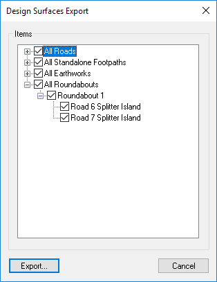
This option enables you to export any of the design surfaces to as DXF polyface mesh entities.
You are shown a list of all the available design surfaces, and can individually choose which ones to include in the exported file.
This DXF output file contains the 3D triangulated surface of the survey model represented as a Polyline mesh. You will find this useful if your application requires a pre-triangulated 3D surface, and can import a polyline mesh.
This DXF output file contains the 3D triangulated surface of the survey model represented as 3D FACE entities. You will find this useful if your application requires a pre-triangulated 3D surface, and can import 3D Faces.
This file format is suitable for loading into the popular drainage design and simulation application. Although Microdrainage is capable of importing a DXF itself, you may prefer to utilise the pre-triangulated surface from Site3D. Microdrainage can import the pre-triangulated surface data as a PWF file. It can then obtain accurate ground levels from this surface.
The STL format is used by some 3D modelling systems and 3D printers. The output represents the 3D ground surface, extruded to a thickness appropriate to the site size.
This output option will produce a text file containing the X,Y and Z coordinates of all the 3D items in the survey model. It contains only points (no lines).
This option produces an ascii file of XYZ coordinates at a regular grid spacing, representing the 3D ground model surface. This type of regular grid data is sometimes referred to as a DEM (Digital Elevation Model) or a DTM (Digital Terrain Model).
When the option is selected you are prompted to choose the desired grid spacing, before specifying the output file.
This option is simlar to the Surface to Gridded ASCII XYZ (*.xyz) but saves with .asc formatting.
This option produces a file containing Virtual Reality Markup Language (VRML) representing the 3D surface model.
This option exports all surfaces to a Land XML file.
This option exports a single surface to a Land XML file.
When the option is selected you are prompted to choose the desired surface to export, before specifying the output file.
When substrata have been used in the project this option is available to output them to a DXF file in the form of Polyline Mesh entities.
When substrata have been used in the project this option is available to output them to a DXF file in the form of 3D FACE entities.