The Setting-Out tools are for the easy annotation of road setting-out information. Setting-out information is usually required on the finished drawings, so that the design can be accurately set-out on-site.
The annotation is dynamic, and as such automatically updates itself when the design items to which it refers are changed. A setting-out table is therefore never out-of-date, or requiring regenerating.
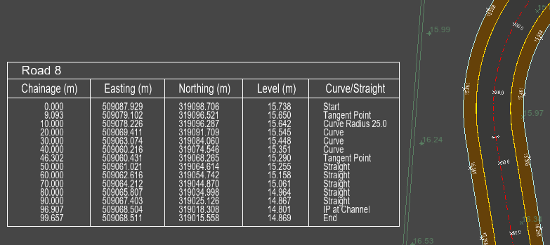
Here is an example of a centreline setting-out table displayed next to the road to which it refers:
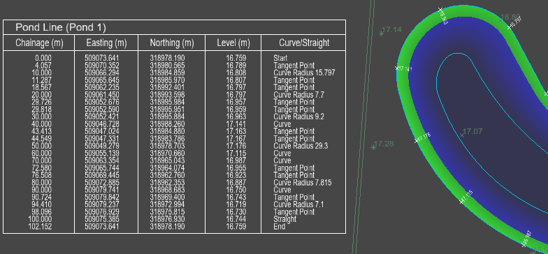
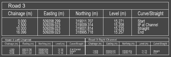
A setting-out table can be generated from any designed item line, here is an example of a pond setting-out table:
Back of Footway levels are automatically annotated where a standalone footpath is junctioned with another footpath/footway. If the terminated footpath is narrower than 2m, a single annotation is shown on the back of footway of the joined onto path at the centre of the junction. If the terminated footpath is 2m or wider, levels are shown on the back of footway of the joined onto path at the edges of the junction. This is demonstrated in the following example:
To access the Setting-Out tools, click the ![]() button on the main toolbar.
button on the main toolbar.
You will see this toolbar appear on the top left of the plan view window:


Select this button to add a new setting-out table for a road.
You will be prompted to select a design line from the drawing. As you move the mouse cursor the nearest design line is highlighted. Click to select.
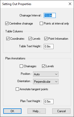
If you select a non-centreline design line, the following setting-out properties window is shown:
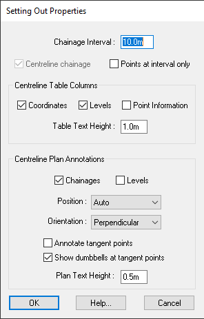
Selecting a centreline will open an expanded version of the setting-out properties window:
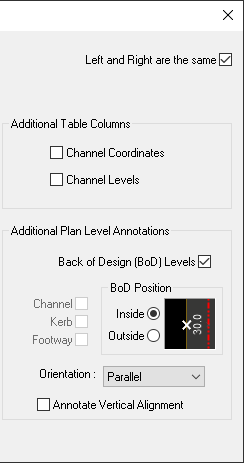
By default the Left and Right are the same checkbox is ticked, so any additional table or plan annotation properties will apply to both the left and right sides of the centreline. For example, ticking the Channel Levels checkbox will add both the left channel levels and right channel levels columns to the table.
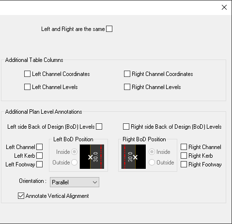
If you un-tick the Left and Right are the same checkbox the window will expand, allowing you to set separate left and right side properties:
After selecting your desired properties and clicking the OK button you will prompted to choose a position for the setting-out table on the drawing. The outline of the table is shown next to the cursor so that you know exactly how big it is, and you can position it accurately relative to the rest of the drawing features.
Select this option to remove a setting-out table from the drawing.
You will be prompted to select an existing setting-out table. As you move the cursor over the drawing the closest design line and associated setting-out table will be highlighted with a red border. Click near the table you want to delete and it will disappear.
Note: If necessary, the Undo facility can be used to put the table back.
Select this option to reposition a setting-out table.
You will be prompted to select an existing setting-out table. As you move the cursor over the drawing the closest design line and associated setting-out table will be highlighted with a red border. Click to select the table, its outline will then display next to the cursor so that you can accurately reposition it. Click again to reposition the table to the mouse coordinates.
Select this option to change the size of a setting-out table.
Depending on your final drawing scale, you may want to resize the setting out tables (for example, for legibility, or to fit then into the space available).
You will be prompted to select an existing setting-out table. As you move the cursor over the drawing the closest design line and associated setting-out table will be highlighted with a red border. Click near the table you want to resize.
The table's outline will then display, stretching as you move the cursor position. The top/left corner of the table remains fixed, while the bottom edge stretches to the cursor position. The right edge moves to maintain a constant aspect ratio of the table outline.When you have stretched the table outline to the desired size, click again and the whole setting out table will redisplay at the specified size, with the text also sized accordingly.
Select this option to view or modify the properties of a Setting-Out Table.
You will be prompted to select an existing setting-out table. As you move the cursor over the drawing the closest design line and associated setting-out table will be highlighted with a red border. Click to re-open the setting-out table properties dialog, allowing you to see and modify the table properties.
Choose the distance between annotated points along the length of the design line.
This option can only be toggled when adding a setting out table to a channel line, top-of-kerb line or the back-of-footway.
 With this option turned on, the annotation points will match the centreline chainage. The setting-out points will be located perpendicularly to the centreline at the centreline chainage.
 When turned off, the annotated chainage will match the actual distance along the line.
Note: The chainage for the point perpendicular to the centreline start point is set to the centreline start chainage. Usually, this results in the line having a 0.0 chainage point perpendicular to the centreline start point. This also means the start chainage of the line may be negative if extending beyond the start or when capping the start of the road.
With this option turned on the setting out table will only annotate points at a regular chainage interval, as well as the start and end point.
Note that with this option on, you will get limited information in the "Curve/Straight" table column.
Under the Table Columns section you can toggle whether the setting-out table contains columns for the annotated line's coordinates (easting and northing), levels, and additional point information (Curve/Straight).
For centrelines you have the option to add Additional Table Columns to the table for the left and right channels.
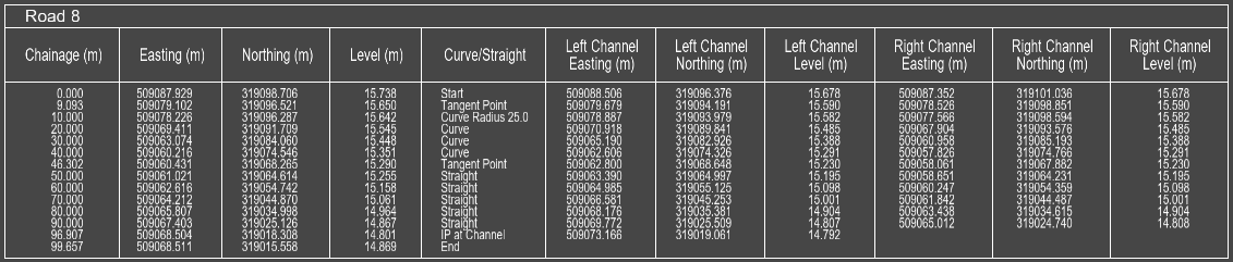
The table text height sets the size of text in the cells of the table. This will scale the entire table. Below is a centreline setting-out table with table text height set to 1.0 and setting-out tables of the roads channels with text heights set to 0.5:
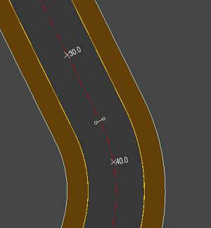
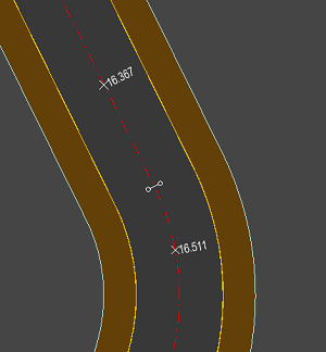
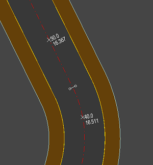
After adding a setting out table, crosses are drawn along the line at the corresponding chainage interval. You can choose to also have the chainage values annotated next to the crosses, or the level values, or both:
 Auto: Draws annotations on the visual right hand side of the annotated point. Intended to place text for left-to-right reading of the annotations.
Relative to the forward chainage direction, the points may swap from being on the left of the line to being the right of the line.
 Left: Draw all annotations on the left hand side of the line, relative to the forward chainage direction.
 Right: Draw all annotations on the right hand side of the line, relative to the forward chainage direction.
 Centre: The annotation text centre-aligned to the annotated line. The setting-out points are marked with a perpendicular tick instead of a cross.
The orientation dropdown is disabled and forced to perpendicular when this annotation style is set, as it is not compatible with the parallel orientation option.
 This shows the perpendicular orientation for plan annotation texts, the baseline of the text is perpendicular to the line that is being annotated.
 This shows the parallel orientation for plan annotation texts, the baseline of the text runs parallel to the line that is being annotated.
This option allows you to toggle whether you get setting out annotations drawn at the tangent points of the line in the plan view.
It may be beneficial to turn this off in cases where this would create overly crowded setting-out information.
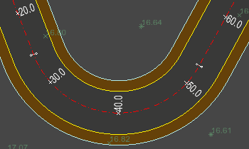
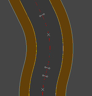
When a setting-out table is present for a road, annotation is also added on the plan drawing of the road. By default, dumbbell symbols are drawn at the curve tangent points along the centreline, as shown in this example:
The Show dumbbells at tangent point option allows you to choose whether to have the dumbbells shown or not.
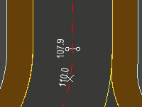
When combined with the Annotate tangent points option the annotation is further offset from the line to avoid overlapping the dumbbell symbol:
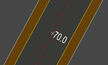
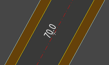
This specifies the size of the annotation text for the line annotation (rather than in the table). The chainage intervals are annotated on the centreline with a small cross with the chainage distance written next to it. The value given represents the height of the text characters, measured in model units. A typical size would be about 0.5 metres (or about 2 ft).
The following image shows the 50m, 60m and 70m chainage annotation points along a section of road centreline:
 This example has the text height set to 0.5m
 This example shows the text height set at 0.7m
This setting also affects the back of design annotation (see below).
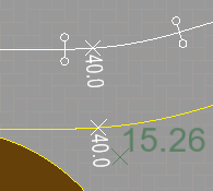
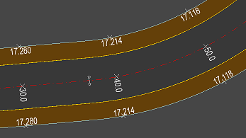
As well as the centreline chainage, it is often required to annotate the back of design levels at each chainage interval. In the Additional Plan Level Annotations section you can choose additional design lines to create level annotations for.
By default the Back Of Design Levels checkbox is ticked.
By back of design we mean the design line furthest from the road centreline on each side. For example, if a footway is present then the back of footway is the back of design. If there is no footway then back of design will be the top of kerb, if a kerb is present. If no kerb is present, then the channel is the back of design.
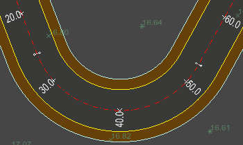
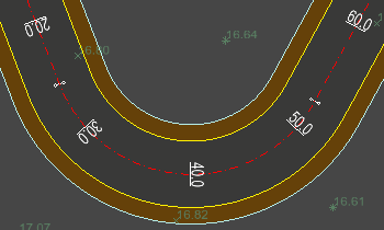
The default position option is for back of design levels to be annotated on the inside, which means the annotation will be placed on the side of the line that is closer to the centreline. Sometimes it is undesirable for the back of design annotation to be placed on the design surface, so you can toggle the position to annotate the outside.
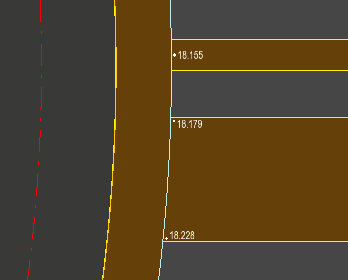
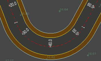
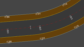
This example demonstrates what will be annotated when Back Of Design Levels is ticked.
The road on the left has the annotation position set to outside. The road on right is set to annotate on the inside.
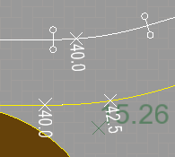
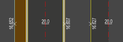
Un-ticking the Back Of Design Levels checkbox allows you to specify any combination of additional level annotations:
When Back Of Design Levels is unticked the channel levels will always be drawn inside the road, and the top of kerb levels will be drawn outside. This is to prevent confusion and stop them from overlapping. The Back of Design Position will affect the position of the back of footway levels.
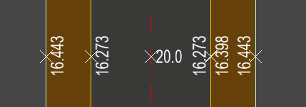
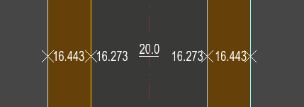
By default the additional centreline annotations run parallel to the annotated line. This is demonstrated in the above images. The orientation drop down allows you to swap between parallel and perpendicular text orientation. Below is an example showing perpendicular additional level annotations:
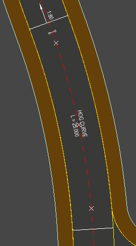
This option will add annotations for the vertical alignment along the road centreline. The vertical curves of the road will be annotated as either a hog or sag curve with the length and lines indicating the extent of the vertical curve. Straight grades are annotated with the direction arrow and a gradient annotation, for longer sections of road the annotations will be at the start and end of the extent of the gradient, for short sections of road the gradient will be annotated in the middle.