In Site3D you can apply automatic surface contouring to roads, paths, 3D surveys, and earthworks. The contour options window allows you to choose how the contours are displayed.
You can enter the roads and path contour options from the ![]() centreline tools toolbar.
From this toolbars, click the
centreline tools toolbar.
From this toolbars, click the ![]() contours button.
contours button.
The contour options will apply to all the roads in your design. You can set contours for a specific road from the Road Properties window.
For an earthwork or pond, after pressing the ![]() earthwork tools button, select or create an earthwork and click the
earthwork tools button, select or create an earthwork and click the ![]() contours button.
contours button.
The contour options will apply to the currently selected earthwork/pond.
For survey contours, from the main toolbar, click the ![]() contour surface button.
contour surface button.
For earthworks you will see the standard contour options window. Road contouring and survey contouring expand on this window with additional options, see further below for more information.
Clicking the contour button on the earthworks toolbar will open the following window:
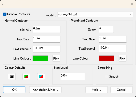
To remove contours that you have set, untick the Enable Contours box and press the OK button.
The default start level for contours is at zero datum. This ensures that you get a contour at a multiple of the height interval you set. For example, for a 0.5m interval, contours would occur at 0.0m, 0.5m, 1.0m, 1.5m ... 99.5m, 100.0m, 100.5m etc.
However, you can change this value to start at any level. For example, setting the Start Level to 0.1m (with a height interval of 0.5m) would result in contours at 0.1m, 0.6m 1.1m ... 99.6m, 100.1m, 100.6m etc.
Sometimes you want to generate just a single contour at a particular height. You can do this by setting the Start Level to the desired single contour height, and make the Interval very large, so that the second contour will not occur within the level range of your design.
Specify the height interval which contours will be generated at.
The purpose of prominent contours is to highlight a greater interval that is a multiple of the normal contours. For example, when set to 5, every fifth contour will be a prominent contour, with four standard contours inbetween (so, when using the default 0.5m interval, a prominent contour will be generated at every 2.5m interval).
The contours are annotated with their level for visual display purposes. The size of the text annotation can be entered here. The value given is the character height of the font as it will appear, in your working units, on the plan view.
If desired, you can specify a different annotation sizes for the prominent contours.
The annotation of the contour height is repeated at regular intervals along each contour. You can specify that interval here. If no annotation is desired, then enter a value of 0 (zero).
You may enter a different annotation interval for the prominent contours.
The colour that the contours will be drawn using. You can click the Pick button to select a different colour.
The buttons select various default colour schemes for the normal and prominent contours. The greyscale scheme can be useful for making the contours less dominant on a drawing.
By default survey contours are drawn using the green/red scheme, and design contours using the blue/red scheme.
When the Apply Smoothing box is checked a smoothing algorithm will be applied to the contour lines. This is not recommended for roads/paths but can be useful for smoothing out survey contours.
Click this button to apply your contour settings and go to the Contour Annotation Lines toolbar to manually position the contour elevation annotations.
Manually positioning the elevation annotations will override the Text Interval setting which will otherwise be used.
Clicking the contour button on the road toolbar or path toolbar will open the following window:

In addition to the standard contouring options, you can select which design items get contoured. By default the road carriageway is included. You can choose to also contour the footpath and kerbs, for example.
Clicking the survey contour button on the main toolbar will open the following window:

From the drop down menu, located near the top of the window, you can select which model you want to apply the contouring to. By default this is set to the current survey.
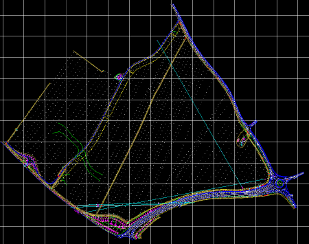
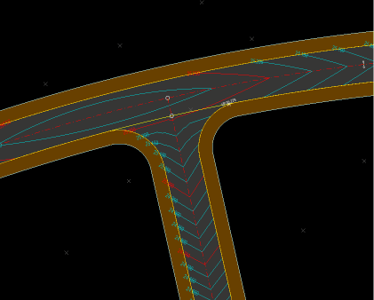
The first of the following pictures show a survey in plan as loaded from file. The second picture shows the survey with 0.5m contours.