The roundabout properties windows is shown whenever a new potential roundabout is detected. For example, when two roads meet at their ends. It is also shown when you select to modify a roundabout.
To create a roundabout you simply use the road design tools to place the start or end of one road at the same position as the start or end of another road. Both roads must have some carriageway width as specified with the Create Channels function.
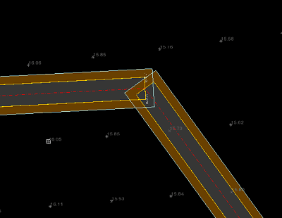
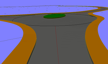
This example shows two roads placed with their ends at the same coordinate.
Use the ![]() snap to point toolbar option to ensure the ends of the roads are positioned precisely at the same point.
snap to point toolbar option to ensure the ends of the roads are positioned precisely at the same point.
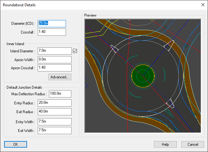
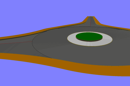
When a potential roundabout is detected the Roundabout Properties window is shown with a preview of how the roundabout would look.
Note: At initial creation the roundabout will have only two arms (joining roads). Extra arms can be added after you have confirmed the creation of the new roundabout.
To modify a roundabout click the ![]() roundabout button on the main toolbar and then select the
roundabout button on the main toolbar and then select the ![]() roundabout properties button. Then click on the plan view near the roundabout you want to modify.
roundabout properties button. Then click on the plan view near the roundabout you want to modify.
This value specifies the overall size of the roundabout. The ICD (Inscribed Circle Diameter) is the diameter at the outer edge of the roundabout carriageway (excluding kerb, footway and verge).
This value represents the slope of the carriageway outward from the edge of the Inner Island out to the ICD.
The choice of positive or negative crossfall affects the automated 3D levelling design of the roundabout:
A positive value (e.g. 1:40) means that the carriageway slopes up out from Inner Island. Crown-lines are formed between adjacent junctions such that the inner part of the carriageway falls towards the inner island, and the outer part falls towards the ICD.
A negative value (e.g. 1:-40) would make the Inner Island higher so that water would drain out towards the ICD, and vehicles driving around the roundabout would be at adverse camber.
By default the diameter of the circular inner island is set automatically. Its size increases or decreases with the ICD so as to provide a standard carriageway width on the roundabout.
You can set the inner island diameter yourself to give any desired carriageway width. Click on the check-box to enable entry of the inner island diameter. The resulting carriageway width will be the ICD minus the Island Diameter.
If specified, the apron width (see below) is included within the inner island diameter.
An apron is an overrun strip around the inner island of a roundabout. It is designed for large vehicles which may have a turning circle insufficient to drive around the roundabout using only the circular carriageway.
The apron width is the horizontal dimension from the inner channel of the circular carriageway inward to the kerb at the inner island.
The apron width is included within the diameter value for the inner island. As such, adding an apron to a roundabout design will not alter the circular carriageway width or levelling, but will reduce the size of the non-drivable part of the inner island.
This value represents the slope of the apron. A positive value slopes up towards the centre of the roundabout, so that water would drain outwards to the circular carriageway. A negative value slopes down towards the centre, so that water would drain inward to the kerb at the non-drivable inner island.
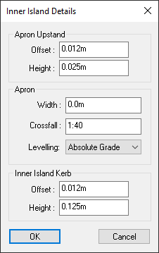
The apron upstand is a kerb that separates the normal carriageway from the apron. The offset and height specify the horizontal and vertical dimensions from the bottom to the top of the kerb face.
A small upstand is often designed to deter standard vehicles from driving on the apron.
The inner island kerb separates the non drivable part of the inner island from the normal carriageway or from the apron if one is specified. The offset and height specify the horizontal and vertical dimensions from the bottom to the top of the kerb face.
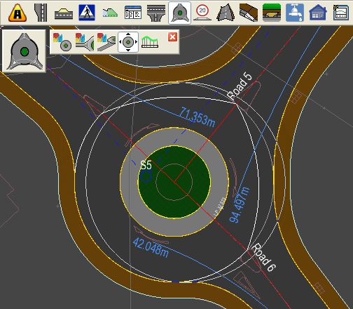
The maximum deflection radius is automatically calculated for each entry road, and annotated on the roundabout. The radius is shown in blue when it is within the given maximum, and in red when it exceeds the limit.
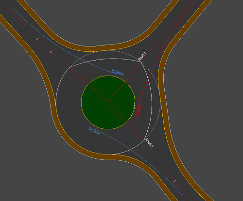
Note: This example shows entry radius for driving on the left side of the road, as in the UK.
The maximum deflection radius is the maximum radius arc a vehicle could drive on when approaching and entering the roundabout. The radius passes no closer than 1m to the kerb, the road centreline and the inner island, and starts no further than 50m back down the road.
Note: Display of the maximum entry deflection radius can be turned on/off on the Layers Window.
Here you can specify the default values for the entry and exit of each roundabout arm. These values will be used for any new arm for the roundabout. This will apply to the initial two arms when the roundabout is first created, and any arms subsequently added.
If you are editing the roundabout (rather then creating it) these values will not change the properties of the existing arms.
Use the ![]() Edit Roundabout Junction button to design the individual roundabout arm junctions.
Edit Roundabout Junction button to design the individual roundabout arm junctions.
You can reposition a designed roundabout to a slightly different centre coordinate. This can often be useful for achieving the required entry deflection radii, or to avoid encroaching into nearby land.
To pick up and move a roundabout, select the ![]() roundabout tools and the
roundabout tools and the ![]() move roundabout button.
move roundabout button.
Select the roundabout on the plan view (they will highlight as you move the mouse near).
The roundabout ICD circle is shown and moves with the mouse. Click to place in the new position.
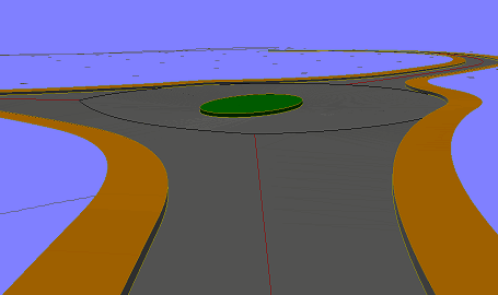
The roundabout will instantly recalculate itself in the new position, retaining all its design properties.
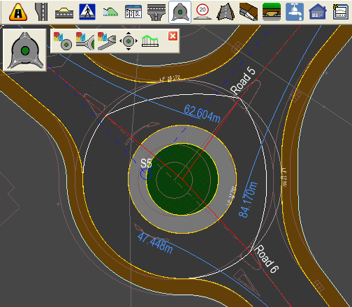
This example shows the above roundabout moved slightly to the left.
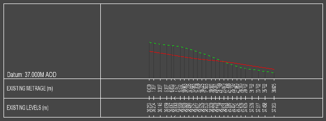
A longsection drawing can be displayed for the various design lines on a roundabout. This includes the central island channel line, the crown lines, and the outer channel lines from each entry to exit.
To display a longsection, select the ![]() roundabout tools and the
roundabout tools and the ![]() roundabout longsection button.
roundabout longsection button.
You will see the various lines highlight on the roundabout as you move the mouse around.
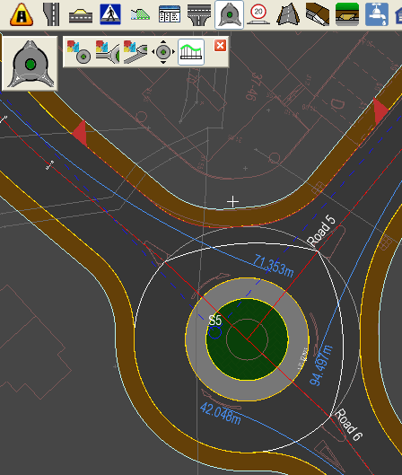
This examples shows the selection of the channel entry to exit line on the northern edge of the roundabout.
Click to select the desired line. A longsection view window is shown with existing and proposed section lines: