The surface shape of an earthwork is defined by a collection of 3D design lines. The outer design line must be a closed line (complete boundary) and may be interfaced to existing ground. There are a number of facilities to assist with defining the design lines.
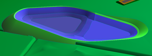
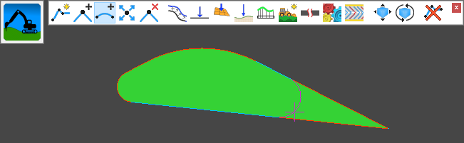
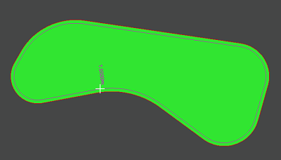
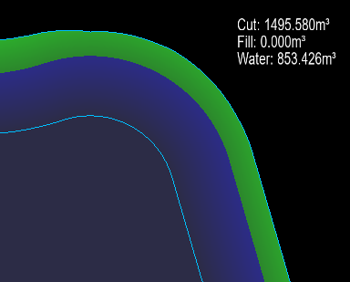
Here is an example of a simple pond, defined with four design lines and interfaced to ground at its edges:
To access the earthwork editing facilites click the ![]() button on the main toolbar. (See here for more details)
button on the main toolbar. (See here for more details)
This is the Earthworks/Ponds toolbar:
The Tanks toolbar is very similar but has some changes:
Earthworks comprise of a set of 3D design lines which describe the 3D surface. There is a range of facilities for designing the 3D lines in both horizonal and vertical.
To create a new earthwork design line click the ![]() button.
button.
The mouse cursor will be shown as a cross when over the drawing, indicating that you should click the start position for the line.
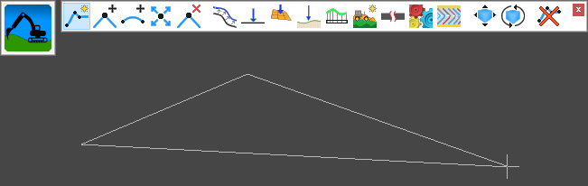
After clicking the start point, a line will be shown stretching to the mouse cursor position. Click the next point to place the line, and continue placing further IPs (Intersection Points) to describe the path of the line.
From the right click menu you can select Finish to add the new line or Cancel to exit the tool without adding the new line.
To place the points accurately, you can use the various snap options on the snap toolbar, and make temporary construction lines using the construction line toolbar.
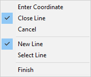
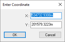
Also, you can right-click the mouse to get a menu where you can select Enter Coordinate to type the desired coordinate on the keyboard.
When you have finished placing the IP points for your line path, right click the mouse and select Finish from the menu.
You will see that the last point joins to the first point, forming a closed loop. Closed loop is the default setting for earthwork design lines.
You can switch between a closed line and a non-closed line using the right-click menu.
Note: In order for the earthwork feature to have its own surface, you must ensure that the outermost design line is a closed loop.
The Select Line option from the right click menu allows you to pick a line from an imported drawing. This will then create a new earthwork line with the same horizontal information.
This option is for modifying the path of an Earthworks design line, by adding one or more IPs (Intersection Points).
Select one of the straight sections between two existing IPs (they will highlight as you move the mouse close). Then position the new IP at the desired location.
This option is for putting the curves on your Earthworks design line.
Click on an IP point, or existing curve, and you'll see the filleting arc passing through the cursor position. Move the mouse to resize the arc, and click to place it.
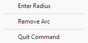
You can select an exact radius by right-clicking the mouse and selcting Enter Radius from the menu.
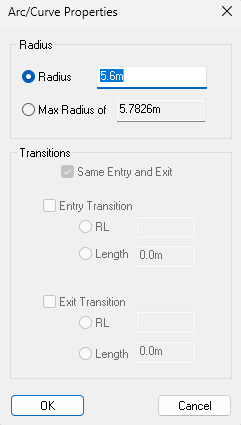
You can enter a specific radius, or select the maximum radius which is shown. The maximum radius will fillet the angle with a curve stretching all the way to the nearer of the neighbouring IP positions.
This option is for moving the path of a earthworks design line, by repositioning one or more of the IPs (Intersection Points).
Select an IP on an earthworks design line (they will highlight as you move the mouse near) and move it to where you want.
This option is for changing the path of an Earthwork Line by deleting one or more of the Earthwork Line's IPs (Intersection Points). If you need to delete a whole design line look at the Delete an Earthwork Line option.
Move the mouse cursor near to the IP which you want to delete (they will highlight as you move the mouse near) and click to delete.
This option is for deleting an entire design line from the earthwork.
Select the design line you want to delete (the lines will highlight as you move the mouse cursor near to them). When you click the mouse you will be asked to confirm the deletion.
After the deletion the earthwork will be updated with the remaining design recalculated accordingly.
If you want to reinstate the deleted line, you can click the Undo button.
Ponds and Earthworks often require specific grading between design lines. This tool can help to achieve this by creating a parallel design line.
Starting with at least one design line on the earthworks, select the ![]() button.
button.
Move the mouse to indicate the offset distance for the parallel line.
Note: A specific offset value can be entered by right-clicking the mouse.
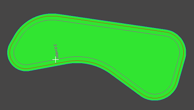
A series of parallel design lines can be used to define a set of stepped grades.
When using the parallel tool ![]() you can right click to see other options:
you can right click to see other options:
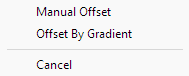
If you select Manual Offset you can enter a specific distance to offset the new parallel line by. The offset side and distance will default to match the rubberbanded position before right-clicking.
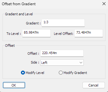
If you select Offset By Gradient you can choose a level/gradient as well as the offset distance. Again, the offset side and distance will default to the rubberbanded position.
The level of the design lines can be set after their creation using the following options:
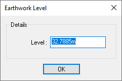
When editing a pond or earthwork, any of the design lines can be set to a specific level, behaving similarly to a contour line.
When you select this option you will be prompted to select a design line from the screen. The design lines highlight as you move the cursor near. Click to select. You can then enter the desired level for the design line:
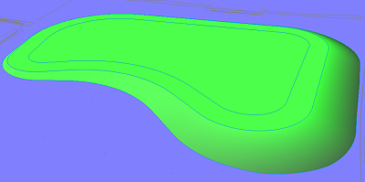
This image shows an earthwork with two design lines (and interfaced down to ground at the edge).
Both design lines are currently at the same level. We can change the level of the innner line:
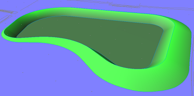
This image shows the earthwork after dropping the level of the inner design line.
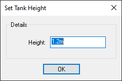
This tool is used to set the height of a tank. This defines the level difference between the bottom and top surfaces of a tank and is determines the maximum storage volume of the tank.
Pressing this button will bring up the Set Tank Height window where you can input the desired tank height.
An earthwork design line can be levelled to a plane at a specified gradient. For example, this can be useful for the base of a pond, so that the water drains in a specific direction.
When you select this option you will be prompted to select a design line from the screen. The design lines highlight as you move the cursor near. Click to select. Then you can specify the required slope:
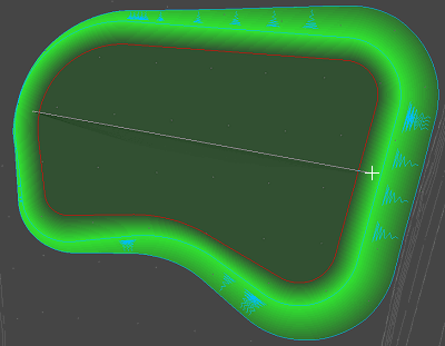
First, specify the direction of the slope (the line of maximum gradient).
You do this by clicking two points to define a the line of maximum gradient for the slope.
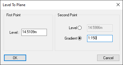
This window is then shown to define the slope gradient.
Give the Z-level for the first point. For the second point you can either specify its Z-level too, or you can give the specific gradient of the slope.
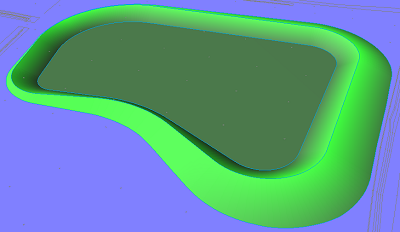
This image shows the earthwork before the slope grading is applied. It is the inner design line that will be levelled.
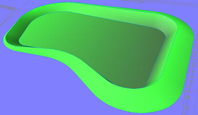
This image shows the earthwork after the inner design line has been levelled to a slope of 1:20.
This option can be used to level an earthwork design line so that it sits exactly on the current surface.
When you select this option you will be prompted to select a one of the earthwork design lines from the plan view. The design lines highlight as you move the cursor near. Click to select. The selected line will be instantly levelled onto the current survey ground surface.
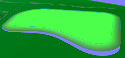
This image shows an earthwork with two design lines. Both have constant levels all the way round, with the inner line being higher than the outer. Both are above the existing ground surface.
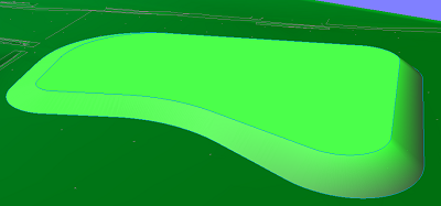
This image shows the earthwork after the outer line is levelled to the ground surface.
Note: The grade between the inner and outer line will vary all the way around the earthwork. If a constant grade is required then the interfacing function should be used.
After pressing the longsection button on the toolbar, a design line can be picked from the earthwork to open a longsection view of the selected line.
This button opens the interfacing options of an earthwork. The earthwork interfacing options are almost the same as the road interfacing options, except that the earthwork interfacing options only apply to the selected earthwork and an earthwork can only interface outward from the outermost earthwork line.
The interfacing window is covered in depth in the Road Interfacing help page.
Using the Split Line tool you can cut a closed line into an open line.
Here you can set the properties of the selected earthwork, such as the name, display style, and water level or freeboard of a pond.
If the earthwork type is a standard earthworks or a pond, the earthwork type can be swapped between pond and earthwork.
See the Earthwork Properties page for more information.
Here you can set the automatic contouring for the selected earthwork surface.
See Automatic Surface Contouring for more information.
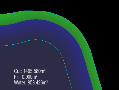
After creating an earthwork, the annotation is automatically placed on the plan. The annotation is placed in the largest area of the earthwork. This will also be recalculated after any design change. While this often does a good job at placing the text the text may still overlap other design items on the site or texts on imported drawings.
If you click the Move Annotation button you will highlight the nearest earthwork annotation text, even if it is not the currently selected earthwork. If you click with an annotation selected you will see the new textbox location and a line going from the earthwork to the centre of the box:
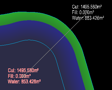
If you click again the textbox will be manually positioned to the indicated location:
To finish right click and select Quit Command from the right-click menu.
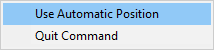
To revert back to automatic positioning you can use the Move Annotation tool to select an annotation, then right click and select Use Automatic Position, this will revert the selected annotation back to automatic positioning. Alternatively, you can enter the Move Annotation tool and right click without having an annotation selected. Then, from the right click menu, select Use Automatic Position. This will allow you to select multiple annotations in a row to set them back to automic positioning. When you are done you can right click again and untick Use Automatic Position to return to manual text position or select Quit Command.
The current annotations contents are as follows:
Using the move tool you can click to select the point to move the earthwork, click again to place the earthwork in a new position. You can alternatively use the tools right click Enter Values option to enter a specific translation.
See Moving an Earthwork for more information.
Using the rotate tool you can click to select the point to rotate the earthwork around, then select another point to get the base angle for rotation, click again to select a new relative rotation. You can alternatively use the tools right click Rotate option to set a rotation origin and specific rotation angle.
See Rotating an Earthwork for more information.


