This facility allows the selected surface (triangulation) properties to be altered.
Note: Before using this facility you will need to have one or more surface model(s) in the project. You can load the a surface when you start the project by opening a ground-survey (for example, from a DXF file). Additional surfaces can be added to the project using the Import option on the File menu.
Once you have a surface model in your project, you can get to the surface properties window from the layers window.
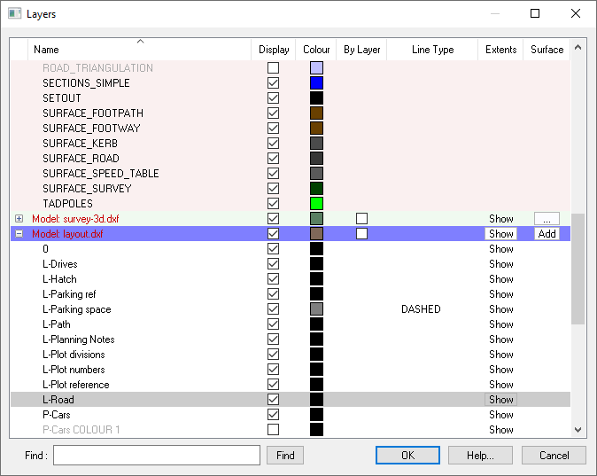
To get to the Surface Properties Window click the surface properties button ![]() which is under the Surface column on the right hand side of the header bar for each submodel that has a surface.
which is under the Surface column on the right hand side of the header bar for each submodel that has a surface.
If the submodel in question doesn't have a surface yet, you can create one by clicking the
![]() button.
button.
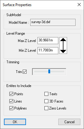
Name of the submodel containing this surface.
The minimum and maximum Z levels by default have been set automatically to include all reasonable surface levels yet exclude any extraneous levels that are obviously not intended to be in the surface. These values can be manually adjusted to include or exclude (threshold) level ranges.
The 3D surface of the current survey model is actually made up of a mesh of triangles (called a triangulation).
Normally the triangles are not shown, but if you want to see them use the Show Triangles Wire Frame option on the View menu. If you also turn on the Survey Height Shading you'll see that some of the triangles at the edge of the site are not used for the surface. This is because they are beyond the extent of the surveyed information. Levels interpolated between items at the edge of the site would be an approximate guess of what ground feature might be in these unsurveyed regions.
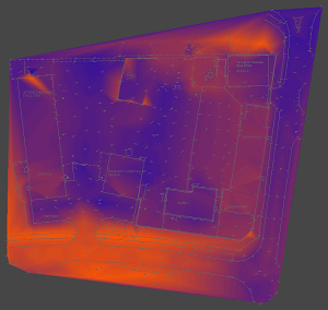 |
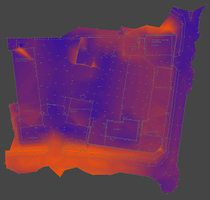 |
| No trimming | Automatic trimming |
Site3D automatically trims off triangles which would stretch over unsurveyed regions at the edge of the site. You can control how much trimming occurs at the site boundary by moving the slider bar next to the Trim option. The result is shown instantly on the Plan View and the 3D view.
If you want no trimming at all, then deselect the Trim check-box.
By default certain drawing entities are not used for making the 3D ground surface. For example text entities rarely have useful surface level values. However, there may be cases where you specifically want to include these other drawing items, or disclude more common drawing entities.
Sometimes a surface may have already been triangulated by some other system, and all you've been sent is the set of triangles in the form of a mesh of 3D faces. If this is the case, you can select the 3D Faces check-box so that they are included in the ground surface for your design model. Normally, 3D Face entities are ignored because the original information from which they were created is usually supplied as well, and Site3D will normally make a better job of forming the triangulated surface than other systems.
Normally levels of exactly zero are ignored for the ground surface because zero is often used to represent an unlevelled feature. However, if your site spans the zero height range then you may decide that an item at exactly zero level is in fact a true level. To include the zero levels in the ground surface select the Zero Levels check-box.