The properties for each layer in the main model can be controlled using Layer States. This feature lets you define custom layer names, colours, and visibility settings, making it easy to switch between predefined configurations (e.g., displaying only drainage layers while hiding others).
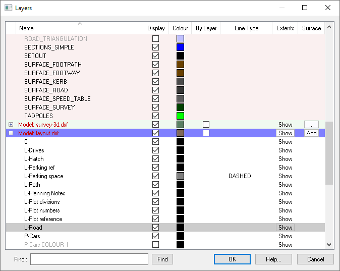
To create a new Layer State, open the layers window and configure the layers as desired. For detailed instructions on adjusting layers, refer to the Layers Window help page. Once your layers are set, click the Save As... button to save the current settings.
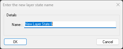
You will be prompted to enter a name for the new Layer State. Once done the new state will then appear in the Layer States dropdown list.
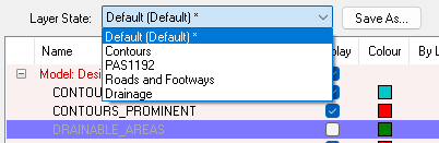
Selecting a Layer State from the dropdown will update the current layers to match the selected settings. If you make any alterations after selecting a Layer State an asterisk (*) will appear next to its title indicating that you are no longer using the same settings. You can update the saved state if desired. The current state also determines the name, colour, and display state (on/off) of newly added layers
To update an existing Layer State, simply re-save the layers with the same name as the Layer State you want to overwrite.
The Default Layer State file enables the use of a company-wide layer state by storing a shared layer state CSV in a central location that can be accessed by all users. This layer state will be used by default in any new projects and will also appear in the layer state dropdown in the layers window.
To create the Default Layer State file, save your Layer State as you normally would. The save location is:
C:\Users\YourUsername\AppData\Roaming\Site3D\layer-states\filename.csv
The filename will correspond to the name of the Layer State in the dropdown. After saving the file, move it to a shared folder that everyone in the company can access.
To use the custom Default Layer State file, right-click on the main model in the Layers window and select "Set Default Layer State File." Then, choose the desired .csv file. Alternatively, you can set this up in the Default Settings Editor by searching for LayerNameLookupFile and entering the full file path, e.g., C:\Program Files\Site3D\layers\my-layers.csv. Once configured, the layer state will appear in the dropdown with the "(Default)" tag.
Note: The Default Layer State cannot be edited within Site3D to prevent accidental overwrites. To update it, save a new file and replace the old one in the shared folder by moving and renaming the file.
Layer State files are plain text files, so you can edit them with any text editor (e.g., Notepad) or spreadsheet program (e.g., Excel). An example file, default.csv, is included in the Site3D installation folder (C:\Program Files\Site3D\layers\default.csv). This file contains a list of layers you can modify.
Note: It's recommended to edit a copy of the file, as the default file may be overwritten during software updates.
Here is an extract of the default.csv file:
ROAD_CENTRELINE,ROAD_CENTRELINES,"RGB(255,0,0)",
ROAD_CENTRELINE_TANGENT_LINE,ROAD_TANGENT_LINES,"RGB(128,128,128)",false
ROAD_CHANNEL,ROAD_CHANNELS,"RGB(255,242,0)",
ROAD_CHANNEL_LOW_POINT,ROAD_CHANNEL_LOW_POINTS,"RGB(0,0,0)",
ROAD_FOOTWAY,ROAD_FOOTWAYS,"RGB(181,238,235)",
ROAD_FOOTWAY_LEVELS,ROAD_FOOTWAY_LEVELS,"RGB(0,0,0)",
ROAD_INTERFACE,ROAD_INTERFACING,"RGB(0,255,0)",
ROAD_JUNCTION_ANNOTATION,ROAD_JUNCTION_ANNOTATION,"RGB(0,0,0)",true
ROAD_KERB,ROAD_KERBS,"RGB(255,200,0)",
ROAD_TRIANGULATION,ROAD_TRIANGULATION,"RGB(192,192,255)",false
ROUNDABOUT,ROUNDABOUTS,"RGB(0,0,0)",
ROUNDABOUT_DEFLECTION,ROUNDABOUT_DEFLECTION,"RGB(72,146,247)",
SETTING_OUT_TABLE,SETOUT,"RGB(0,0,0)",
Lines starting with a # will be ignored, allowing you to add comments to the file.
Each line that does not start with a # must contain the following information, separated by commas:
"Double quotes" are required around the RGB() text because it contains commas.
To use the Uniclass 2, PAS 1192 layering scheme, use the Default Settings Editor to specify the pas1192.cvs file as the default layer states or copy it into the APPDATA\layer-states folder. This file comes with the software. The file location would usually be C:\Program Files\Site3D\layers\pas1192.csv.
Here is an extract from the pas1192.cvs file with the PAS 1192 Uniclass 2 naming convention:
ROAD_CENTRELINE,C-EF_40_50-M3-RoadCentreline,"RGB(255,0,0)",
ROAD_CENTRELINE_TANGENT_LINE,C-Zz_20_70_20-M2-RoadTangentLine,"RGB(128,128,128)",false
ROAD_CHANNEL,C-EF_40_50-M3-RoadChannel,"RGB(255,242,0)",
ROAD_CHANNEL_LOW_POINT,C-Zz_20_20-RoadChannelLowPoint,"RGB(0,0,0)",
ROAD_FOOTWAY,C-EF_40_50-M3-RoadFootway,"RGB(181,238,235)",
ROAD_FOOTWAY_LEVELS,C-Zz_20_20-RoadFootwayLevel,"RGB(0,0,0)",
ROAD_INTERFACE,C-EF_40_50-M3-RoadInterfacing,"RGB(0,255,0)",
ROAD_JUNCTION_ANNOTATION,C-Zz_20_10-A-RoadJunctionAnnotation,"RGB( 0, 0, 0)",true
ROAD_KERB,C-EF_40_50-M3-RoadKerb,"RGB(255,200,0)",
ROAD_TRIANGULATION,C-EF_40_50-M3-RoadTriangulation,"RGB(192,192,255)",false
ROUNDABOUT,C-EF_40_50-M3-Roundabout,"RGB(0,0,0)",
ROUNDABOUT_DEFLECTION,C-Zz_20_70_50-M2-RoundaboutDeflection,"RGB( 72, 146, 247)",
SETTING_OUT_TABLE,C-Zz_35_20-A-CentrelineSettingOut,"RGB(0,0,0)",