This option is for putting the curves on your road centreline path. You can specify a constant radius curve, and optionally have lead-in and lead-out spiral transitions.
You can change the road centreline path at any time during the design process. Site3D will work out all the knock-on effects and update your site accordingly.
On the ![]() centreline tools toolbar, click the
centreline tools toolbar, click the ![]() add arc button.
add arc button.
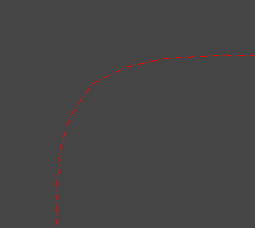
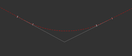
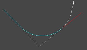
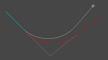
Click on an IP point, or existing curve, and you'll see the filleting arc passing through the cursor position. Move the mouse to resize the arc, and click to place it.
When the tool is active you can right click the mouse to bring up the right click menu. This menu provides a few different options editing centreline arcs:
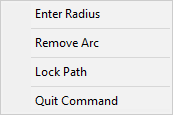
You can select an exact radius (or specify lead-in/out spiral transitions) by right-clicking the mouse and selecting Enter Radius from the menu.
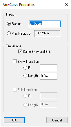
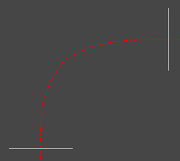
You can enter a specific radius, or select the maximum radius which is shown. The maximum radius will fillet the angle with a curve stretching all the way to the nearer of the neighbouring IP positions.
If you want a spiral transition at either end of the curve then click the box for Entry Transition and/or Exit Transition. The transition is a broad spiral which starts at infinite radius on the straight part of the road and increases in radius to meet the circular curve. Transitions are often required for main highways, whereas small roads in housing estates do not. You can specify the length of the required transition, or the RL value (inner curve radius multiplied by the length over which the transition takes place).
The Lock Path option is available in the right-click menu. Setting an arc to have a locked path affects what happens when you move either of its neighbouring IPs.
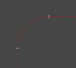
With the arc path locked the arc will maintain its centre point and stretch/contract in length to meet tangentially with the neighbouring IP which is moving. The IP associated with the arc will move its position. Note: You cannot use transitions when the arc path is locked.
With the arc path unlocked the arc IP position will be maintained and the arc position moves such that it meets tangentially with the straight lines to its neighbouring IP positions.
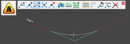
Using the Curve Fit option you can add a best fit curve based on the IPs between the two selected points.
After changing to the curve fit mode you select a point to start the best fit region and a point to end the best fit region. The IPs in-between the two points will be removed and replaced with an arc that best fits the original line. The start and end directions of the line at the two selected points will stay the same and become the tangents of the arc.
If there is only a single point between the selected chainages the point will be filleted with as large a radius as possible.