The longsection properties window allows you to adjust the contents and display settings of the current longsection view.
While a longsection view window is active, click on the Longsection Properties button (![]() ) from the view toolbar on the right edge of the window.
) from the view toolbar on the right edge of the window.
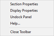
Alternatively, you can right-click within the longsection view window and select Section Properties from the drop-down menu:
You should see the window below:
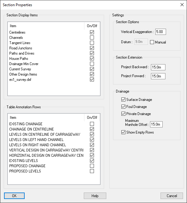
From this list you can toggle which section items are drawn in the current longsection.
For example, you can toggle the drawing of specific ground sections or the channel lines of a centreline longsection.
The longsection drawing will be updated and show the changes immediately.
From this list you can toggle which table rows are annotated for the current longsection.
For example, you can toggle the annotation row for existing ground levels.
The longsection table will be updated and show the changes immediately.
Vertical Exaggeration allows you to set the scaling of the longsection along the vertical axis.
The Datum box will be grayed-out by default but will display the datum that was automatically selected by Site3D according to the level range of the section drawing.
If you tick the Manual check-box adjacent to the datum text field, the text field will become active allowing you to enter a specific datum level of your choosing.
Here you can specify additional section length to include in the section, projected backward/forward from the start/end points of the section path.
Backwards specifies the projected distance beyond the start chainage for which the ground profile and other design items are shown.
Forwards specifies the projected distance beyond the end chainage for which the ground profile and other design items are shown.
From the drainage section you can toggle the projected drainage along the length of the centreline as well as the inclusion of drainage rows in the longsection.
Note: Drainage crossing through the section get drawn as pipe intersections instead of projecting along the section. This is toggled separately from the Section Display Items list, Conduit Intersections.
These items toggle the inclusion of the drainage network on the longsection. If ticked that drainage network will get projected along the centreline longsection and the associated table rows will be included.
If there are no manholes which can be projected or both the Surface Drainage tickbox and Foul Drainage tickbox are unticked, no projected drainage will be shown and no drainage rows will be included in the table.
This toggles whether manholes that are marked as private will be included.
This specifies the maximum distance a manhole can be in order for it to be projected onto the longsection. Specifically, this is the maximum perpendicular distance from any point along the centreline.
For example, with a value of 15m, any manholes that lie within 15m from any point along the road centreline will be included in the longsection drawing. Manholes that are beyond the specified distance will not be included.
When only one of the drainage network types is included in the longsection (either only surface drainage or only foul drainage), this option toggles whether to include an empty annotation row where the missing drainage network type would be annotated.
This allows you to have a consistent drainage row layout across centreline longsections, even if one of the drainage types in not present in the longsection view.