On the ![]() drainage size and level tools click the
drainage size and level tools click the ![]() button.
button.
You are then prompted to select an outfall manhole from the Plan View:
After selecting the outfall manhole, the options window is shown for the drainage network associated with the outfall:
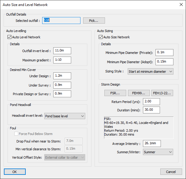
In the Auto Size and Level Network window you can set the auto sizing and auto levelling properties, pressing the OK button will then perform the specified auto sizing and levelling of the drainage network.
The Auto Level Network tick-box at the top of the Auto Levelling area can be deselected to prevent the auto levelling being performed.
Similarly, the Auto Size Network tick-box at the top of the Auto Sizing area can be deselected to prevent the auto sizing being performed. You cannot be deselected both options, as there would be nothing left for the facility to do.
For storm drainage networks, the automatic pipe sizing is based on rainfall on the contributing areas associated with the drainage network. Contributing areas can be created using the Drainable Area Tools or by manually setting the contributing area in the Conduit Properties.
For foul drainage networks, the automatic pipe sizing is based on the contributing units associated with each pipe, which can be set in the Conduit Properties.
This will show the name of the manhole which was selected. This manhole is assumed to be the outfall of the drainage network and the rest of the connected network will be auto-levelled to flow toward this manhole.
The Pick button can be clicked to re-choose the manhole.
Note: whether a storm or foul manhole is selected determines which other options are available and how the levelling is performed. For example, auto-sizing and levelling the surface water network may result in clashes with the foul network. Whereas, auto-sizing and levelling the foul network will avoid clashes with the surface water network. It is intended that you would do the foul network after the storm network. In other words, the storm network takes precedence for levelling and the foul network works around it.
The drainage network will be levelled to achieve minimum cover depth and minimum grades to achieve cleansing velocity in the pipes.
This initially shows the invert level of the selected manhole. You can modify this to specify your desired outfall invert level.
You can specify the maximum gradient that can be applied to the network when it is auto-levelled.
Here you can specify the minimum cover depths for the drainage network for adoptable drainage located under road/driveway surfaces (Under Design), adoptable drainage elsewhere (Under survey), and for private/plot drainage (Private Design or Survey).
If there are any ponds that have been included as a part of the surface drainage network, you can specify the levelling that is used for the manholes connected to the pond.
A pond will give a fixed level on the drainage network, around which the auto-levelling will operate. You have a couple of choices for how the level is fixed:
The default is Pond base level which means the headwall will be dropped to the base level of the pond, regardless of whether it is placed upon the side slope of the pond.
Alternatively, you can choose Pond level at headwall which means the headwall invert level will be taken from the side slope of the pond at the location of the headwall.
Note: The Pond Headwall option is disabled if a foul network is selected.
Note: The foul drainage options will be disabled if a storm network is selected.
By default, with Force foul below storm deselected, the foul network may pass above the storm network if there is sufficient clearance, otherwise it will drop below the storm network.
When Force foul below storm is selected the foul network will be levelled such that the foul water pipes are below the storm pipes if within the Drop Foul when near to Storm horizontal distance. The default distance of 7m generally covers the width of most roads. In other words, if the foul and storm network are on the same road then the foul goes below the storm.
The Min vertical clearance to storm distance specifies the minimum allowed vertical separation between a foul and storm pipe. This vertical separation distance is for both when the foul passes above or below the storm network.
The vertical clearance can be specified as being either Internal to internal or External collar to collar. With "internal" meaning the vertical separation is measured between the internal pipe walls and "external collar" meaning the vertical separation is measured between external pipe walls plus collar sizes.
The pipe sizing is based in the Wallingford Hydrograph Method, whereby peak flow is determined at all points throughout the network according to the time of flow through the system of the combined input hydrographs derived from the design storm rainfall intensity profile (or for foul from the design units).
This methodology should give a network that will cope with the water from the design input without surcharging back up the system. Full drainage simulation is recommended to check the surface water system is able to cope without flooding for a full range of rainfall events.
The Minimum Pipe Diameter (Private) specifies the smallest pipe diameter which is allowed for pipes that are part of a private/plot drainage run. The Minimum Pipe Diameter (Adopt) specifies the smallest pipe diameter which is allowed for pipes that are part of an adoptable drainage run.
A pipe is classed as private/plot drainage if the upstream manhole has the Private property set in its Manhole Properties.
The default option Start at minimum diameter will ignore any existing sizes of the pipes, and size them to the minimum necessary to cope with the calculated design flow.
Alternatively, the Increase only option will retain all of the current pipe diameters and only increase any where necessary to cope with the calculated flow.
Note: The design storm options will be disabled if a foul network is selected.
The pipe sizing for storm water networks is based on the calculated water volumes to be taken by the pipes. This is based on an average rainfall volume that falls onto the contributing drainable areas associated with each pipe. So, for correct sizing of the pipes you must first add drainage catchment areas or contributing area to the network.
The rainfall data for the storm can be specified using either FSR data (Flood Studies report, M5-60 Ratio R) or FEH99/FEH13 data (Flood Estimation Handbook).
The rainfall data (FSR or FEH data) in combination with the Return Period and Duration is used to calculate an average rainfall intensity for the auto sizing. Changing the rainfall data, return period, or duration values will automatically recalculate the average intensity.
This can also be manually specified by simply typing in the average intensity value directly, overriding the automatically calculated value.
The pipe sizing can be done based on either a typical summer or winter storm profile. This setting will also change the runoff coefficient that is used when calculating the flow from drainable areas.
The summer/winter runoff coefficients for the project be set in the project settings. This can also be overridden per drainable area by setting the summer/winter coefficients in the drainable area properties.
Summer storms tend to be more intense than winter storms and are therefore usually used for sizing the drainage system.
Click the OK button to perform the sizing and levelling of the selected drainage network.
If the network can be sized and levelled to comply with all the specified criteria, then a window will pop-up at the bottom right of the screen to tell you that it was successful.
However, it may be that it is not possible to achieve minimum cover and grades for all the pipes as well as not exceeding the depth of the outfall, or a pond depth. In this case the network will be levelled so that the minimum cover is not maintained all the way to the head of the system. An information window will inform you how many pipes did not achieve minimum cover, and advise the outfall or pond level that would be required to achieve minimum cover throughout.
As well as sizing and levelling the pipes, the manholes will also be updated to the appropriate size and type for the resulting drainage network.