This option generates a longsection view of the boundary network along a run of boundaries between two nodes.
On the ![]() Boundary tools toolbar, click the
Boundary tools toolbar, click the ![]() Boundary longsection button.
Boundary longsection button.
You then select the two boundary annotations between which the longsection should be generated:
Start Node Selection:
End Node Selection:
Any two node annotation can be selected which are connected together on the same side of the boundary. The longsection will be generated for the most direct route between the two nodes.
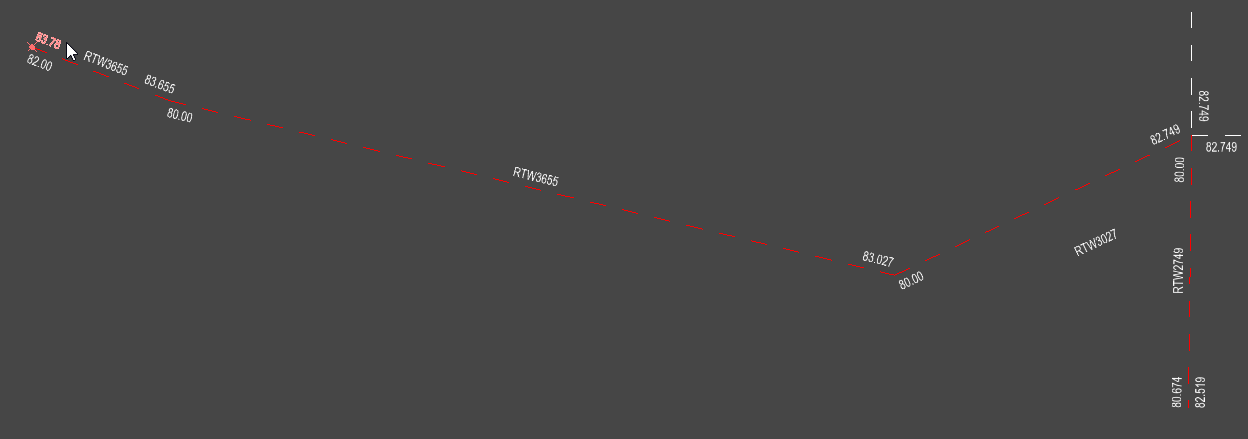
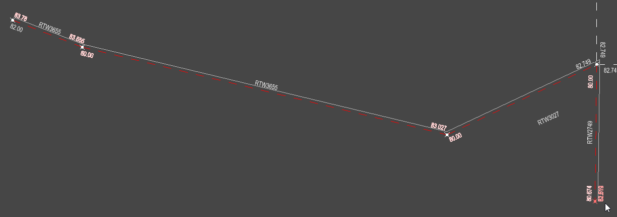
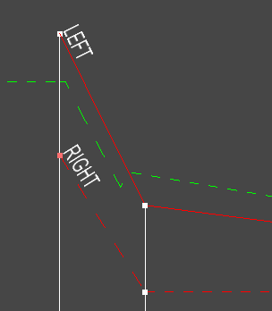
The longsection view window is shown with a fully annotated boundary long-section drawing:

The longsection view illustrates the levels of the boundary run on both sides. The sides are labeled "LEFT" and "RIGHT". These labels are relative to the direction of the run: the left levels are on the left when moving from the first node to the last node. The solid line represents the boundary side you selected during creation, while the dashed line indicates the opposite side.
The toolbar on the longsection window has the following buttons:
![]() Edit Level
Edit Level
![]() Set the Gradient along a Run
Set the Gradient along a Run
![]() Click this button to close the toolbar
Click this button to close the toolbar
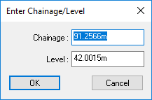
To change a level at a node, click the ![]() button.
button.
You can select one of the nodes on the longsection drawing and move it up/down. The node's joining links also move up/down with it.
You can also right-click to see a menu for further options
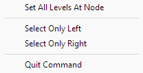
This setting will set all levels at the selected node to the proposed level.
From the right click menu you can select Select Only Left to prevent the selection of right hand levels or you can select Select Only Right to prevent the selection of left hand levels. This is useful when the left and right levels are the same at a given node.
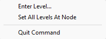
Once an initial node has been selected the right-click menu changes.
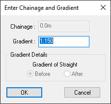
To set the gradient on a link, or a run of links, click the ![]() button.
button.
You should now select the two nodes between which the gradient is to be set. They can be adjacent nodes for setting a single link gradient, or they can be separated by a run of links and nodes.
You will be prompted to select the start node position from the drawing.
As you move the mouse cursor the nearest node is highlighted.
Click to select.
Then you will be prompted to select the end node.
As you move the mouse cursor the nearest node is highlighted.
Click to select.
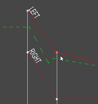
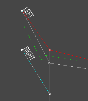
The following images show the difference after setting the left side of the whole run to a gradient of 1:50 (2%).
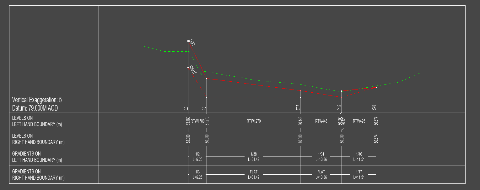
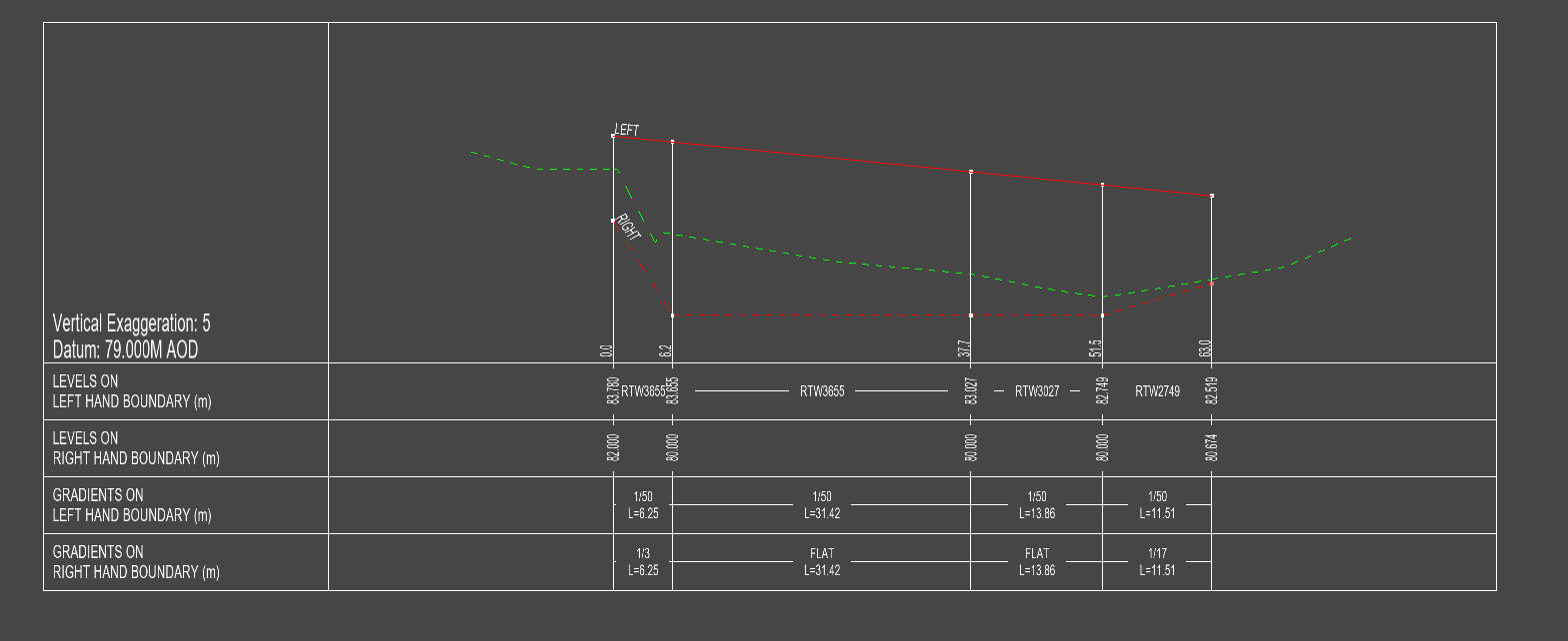
Note: The gradient is set from the first selected node, which will maintain its depth. The depths of all the other nodes in the selected run are adjusted to achieve the specified link gradient.
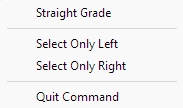
From the right click menu you can select Straight Grade to level the nodes between the start and end to match the straight gradient.
From the right click menu you can select Select Only Left to prevent the selection of right hand levels or you can select Select Only Right to prevent the selection of left hand levels. This is useful when the left and right levels are the same at a given node.