Georeferencing is the process of scaling, rotating, translating and deskewing the drawing to match a particular size and position.
This is very useful when you have loaded data which has not been produced to the same coordinate system as the rest of the project. For example, when a paper drawing has been scanned and put through a raster-to-vector converter, the resultant CAD drawing may have arbitrary size and position.
This is also useful for imported raster images (e.g. TIF or JPG file) which may come with no coordinate system at all. Such images will initially be stretched over the project extent, and you can use this georeference facility to easily locate it into the correct place relative to the other drawings.
The term georeference will be familiar to GIS users, but CAD users may be less familiar with the term, even though the function is very useful for their work. The word was originally used to describe the process of referencing a map image to a geographic location.
To get the Georeference option click the Surface menu and select Georeference.... You will see this window:
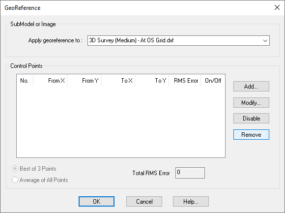
This is a drop down list of imported drawings and images which you can pick and choose to georeference. Currently, you can Georeference only one at a time.
The georeference process simply involves selecting a coordinate on the submodel you wish to move and specifying what coordinate it should represent. When you have picked 3 of these "control points" and referenced those points to their intended coordinates, Site3D can calculate the correct mapping for every point, line, arc, etc... in the drawing. It will automatically be located in the correct position and at the right size.
First you should click the Add... button to specify the first Control Point. You will see this window:
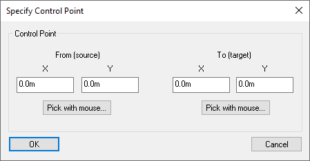
You can type in the X and Y source location, but the most common usage is to click the Pick with mouse... button. When clicked, the windows will hide whilst you select a point on the model by left clicking on the plan view. After choosing a point, the window will return with the X and Y source coordinates pre-filled. Repeat this step for the target coordinate.
Suggested control points: On a map or geographic survey, a grid intersection or a survey station would be a good choice for a control point. On an engineering drawing it might be one end of a dimensioned length on a line that should be horizontal or vertical (and your 2nd control point will be the other end of the line).
You need to Add... at least 3 Control Points so that Site3D can calculate the correct mathematical transformation. It is permissible to give just 2 control points, although this will not allow Site3D to compensate for stretching or skewing of the drawing.
If you enter more than three control points then you can choose how Site3D uses them for calculating the georeference transformation. You will notice that the options Best 3 Points and Average of All Points have become available. But first let us explain the RMS Error...
On the Georeference window, each control point has an RMS Error value. RMS stands for Root Mean Square, which refers to a distance. The RMS Error value is the distance of the georeferenced control point from the vector coordinate which you specified for it. When there are 3 control points the RMS Error values are always zero, because Site3D can calculate an exact mathematical transformation. When there are more than 3 control points then some may show an RMS Error because the georeference calculation is not able to correct for localised deformation of the raster. The RMS Error values will show you which of your control points are likely to be most accurate. You want to have control points with the lowest RMS Error values.
With this option selected, Site3D selects which 3 control points to assign with zero RMS Error, such that the remaining points have the minimum Total RMS Error. This is the default setting, because it guarantees that at least 3 of your control points will be precisely positioned to the target coordinates, and the remaining control points will have minimal inaccuracy.
If you think that all of your control points are equally accurate (or inaccurate!) and no three should be given priority over the others, then select this option. Site3D will place all the control points near to your specified target coordinates such that the RMS Error distance is about the same for each point, and the Total RMS Error is minimal.
When you have more than three control points, the RMS Error values will show you which points Site3D considers to be most accurate. However, you may know which points are actually most accurate and want those to be favoured over the others in the georeference calculations. Therefore you can use the Disable button to prevent a point from being used the calculations. First click the point in the list, so that its Point No. is highlighted, then click the Disable button. The point's On/Off value will be shown as Off rather than On. A disabled point can be easily re-enabled, because when the point is highlighted in the list the button will read Enable rather than Disable.
If you think that the Total RMS Error value is too high, you can experiment with disabling one point at a time to see if the Total RMS Error goes down dramatically for a certain point. This would indicate that the point is either particularly inaccurate, or that you may have entered its position incorrectly.