These options are available from the Road menu, in Centreline Extras.
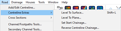
This allows you to set the vertical alignment of a centreline to match the current survey surface.
As shown in the menu you can access this command in a plan view by using the shortcut Shift+L.
After picking this option, select a centreline from the plan view. You should see the following message:
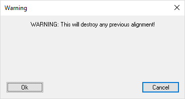
This message is bringing to your attention that the Level To Surface command will change the vertical alignment of the selected centreline, which will remove any previous alignment.
Click Ok to continue and level the centreline to the survey surface.
If you click Cancel the operation will be cancelled and the alignment of the centreline will remain unchanged.
This allows you to set the vertical alignment of a centreline such that it sits on a plane that you specify.
After picking this option, select a centreline from the plan view.
The mouse will change to a crosshair selection cursor for you to select three locations in the plan view. These three points will form a triangle which will be be the basis of the planar surface you are aligning to, based on the Z level of the points.
After selecting three points you should see the following message:
This message is bringing to your attention that the Level To Plane command will change the vertical alignment of the selected centreline, which will remove any previous alignment.
You should then see the following window allowing you to fine tune the points which define the plane you will level the centreline to:
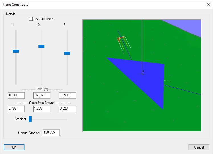
You can tweak the points which define the plane using the vertical bars or fine tune them by manually entering the levels/offsets from the ground surface.
The arrow at the centre of the triangle shows the gradient of the plane.
The Lock All Three option allows you to lock the relative levels of the points that define the plane. This means that while this option is on, any changes to the levels will update the other points to maintain the gradient of the plane. Changing the gradient will not be affected by this option.
A Manual Gradient can be specified which will scale the gradient whilst keeping the existing gradient direction.
Click Ok to level the centreline to the specified plane.
If you click Cancel the operation will be cancelled and the alignment of the centreline will remain unchanged.
This option allows you to modify the chainage that the centreline starts at.
The chainage along the centreline will be recalculated from the new centreline start chainage.
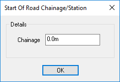
You can input the new centreline start chainage here.
Click Ok to apply the new centreline start chainage.
This option allows you to select a centreline to reverse the chainage direction and have the chainage start from the opposite end of the centreline.
By default the forward chainage direction is based on the order that you create the points when making a new centreline. Or, when using the Select Line option in the right click menu, you choose the forward chainage direction after selecting a polyline to create a new centreline from. See the new road help page for more information.
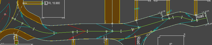
Below is an example of a road which has been added with the chainage going from the right to the left. This is indicated by the label position ("Road 2") on the right hand side of the image:
After using the reverse centreline chainage command on this centreline the chainage starts at the junction and increases from left to right:
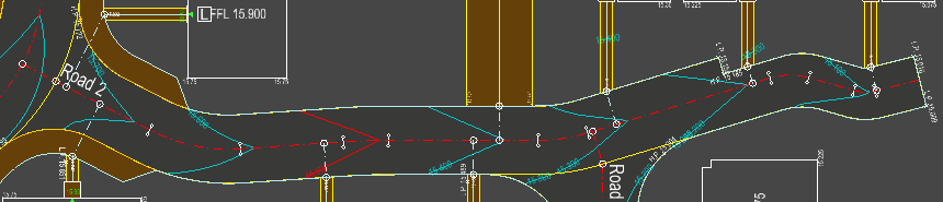
The road design and any attached junctions and design items will stay in the same position they were added. All of the attached design items will have their design chainages updated to match the new centreline chainages.