To access the Design Line Setting-Out tools, click the Tools menu and select Design Line Coordinate Table option.
The Design Line Setting-Out tools are for annotation of generic design lines. For more specific setting out information for roads and footways, refer to the Centreline Setting-Out Table.
Setting-out information is usually required on production drawings, so that the design can be accurately set-out on-site.
The annotation is dynamic, and as such automatically updates itself when the design items to which it refers are changed. A setting-out table is therefore never out-of-date, or requiring regenerating.
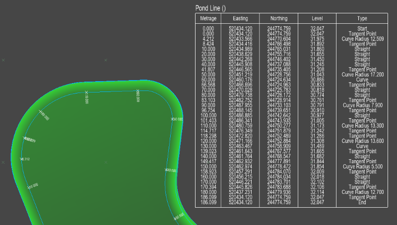
Here is an example of a design line setting-out table displayed next to the pond to which it refers:
After selecting the Design Line Coordinate Table option, you will be prompted to select a design line from the drawing. As you move the mouse cursor the nearest road centreline, interface line or other line from the proposed design model is highlighted. Click to select. The setting-out properties window is shown:
After selecting your desired properties and clicking the OK button you will prompted to choose a position for the setting-out table on the drawing. The outline of the table is shown next to the cursor so that you know exactly how big it is, and you can position it accurately relative to the rest of the drawing features. It is common to position the table near to its design line, such that it does not obscure other design detail. Alternatively, you may wish to neatly line up all your setting-out tables around the edge of the drawing sheet.
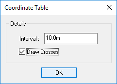
Choose the distance between annotation points along the length of the road centreline.
Tick this option on if you wish to annotate a cross and chainage on the selected design line to indicate where each point in the setting out table references.
To reposition design line setting-out table, or change it properties, simply use the Design Line Coordinate Table option again to select the same design line and respecify the annotation properties. When the new position for the table is chosen, the old table is moved.
To remove a design line setting-out table, use the Design Line Coordinate Table option again to select the same design line, and set the Interval to 0 (zero). When you click OK the table and the related chainage annotation crosses will be removed from the drawing.