To create interfacing along a road, or to reset the interfacing along the full length of a road, first click the ![]() button on the main toolbar and then the
button on the main toolbar and then the ![]() button on the Interface Options toolbar.
button on the Interface Options toolbar.
You will be prompted to select a road from the drawing. As you move the mouse cursor the nearest road centreline is highlighted. Click to select. The interface properties window is shown.
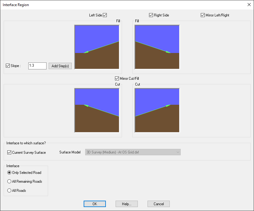
Note: If the road already has interfacing then the existing interface properties are shown in the window, ready to be modified.
At its simplest, the interfacing can be specified with just a single straight grade for the batter slope. This is shown in the example window above. The default slope is set at 1:3, and the checkboxes are selected to mirror the slope up/down as well as left/right.
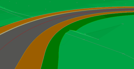
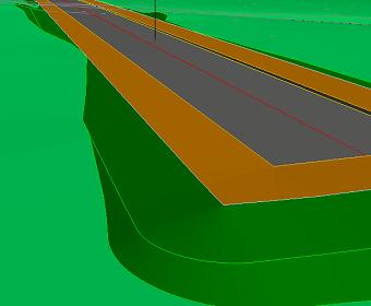
This simple interfacing can be seen in the following example image:
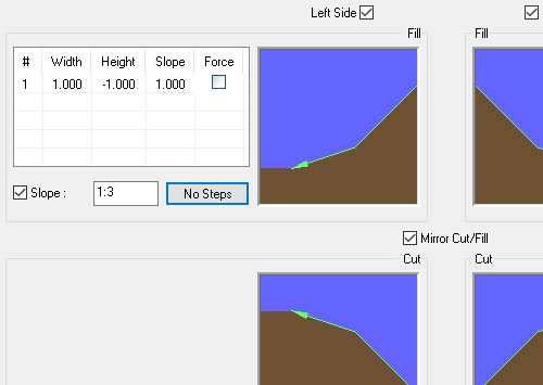
By deselecting the Mirror Cut/Fill checkbox, you can specify a different downward slope to the upward slope.
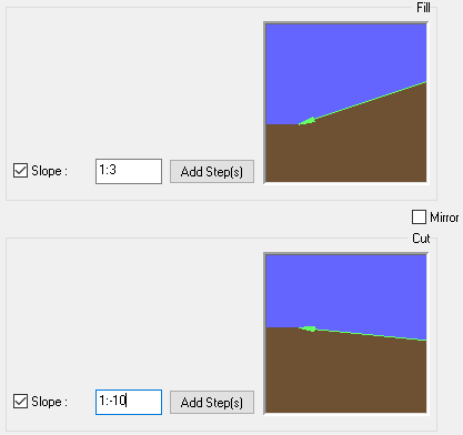
The upward slope is used when the existing surface is above the designed surface and therefore the slope must extend upward to meet the existing ground.
The downward slope is used when the existing surface is below the designed surface and therefore the slope must extend downwards to meet the existing ground.
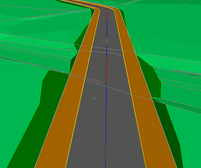
In this example, the immediate foreground section of the road is in cutting, with the interfacing sloping upwards from the back of footpath.
As the road passes over the ditch in the mid-ground and the existing surface drops away, the interfacing slopes downwards from the back of footpath to form an embankment.
Where the road emerges out of the ditch it goes back into cutting, with the upwards interfacing again being in effect.
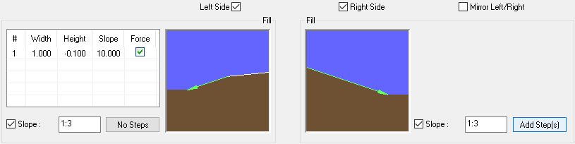
By deselecting the Mirror Left/Right checkbox, you can specify the interfacing slope on the right-hand side of the road to be different to the slope on the left-hand side.
Instead of a single straight slope interfacing, you can insert a series of varying grades to make a stepped interface slope.
When you click the Add Steps button it will show the step properties:
The step has a fixed length, and can be specified as either a width/height pair, or width and slope, or height and slope.
When steps are present, the No Steps button is shown. Clicking the No Steps button will remove all the steps, leaving just the single straight slope.
Multi-stepped interfacing can be used to make more complex constructions running alongside the road.
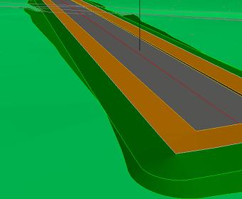
In this example, a road-side ditch has been constructed by having steps down, across, and back up, before grading back to the existing ground surface.
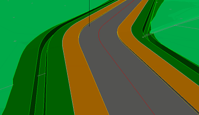
And it looks like this in 3D.
When you click the Add Steps button, the steps list is shown, with one step added by default. To add another step, just click in the next row in the list.
To delete a step, click on it in the list, so that the row highlights, and press the Delete key on the keyboard.
Additionally, you can right click the mouse over any step on the list to see the follwowing menu:
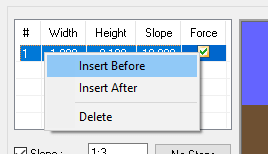
You can select to insert a new step before the selected step, or after the selected step, or you can delete the selected step.
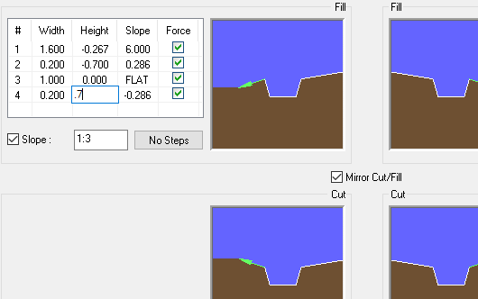
Steps with the Force option set are formed regardless of whether the existing ground would have intersected with the interfacing before the final grade.
Note: When using Mirror Cut/Fill the forced steps are not inverted, only the final step which grades back to existing surface is inverted. This can be seen in the above example, with the forced steps, drawn in black lines, being the same in the upper and lower preview images, whereas the non-forced final slope, drawn in green, go in opposite directions.
When Force is not selected the step will stop if it intersects the ground surface.
However, if the Force checkbox is selected the step will continue to the specified length regardless of whether it pierces the ground surface on the way.
In this example, the first step has been specified as a 1.5m slope at a grade of 1:6 which does not stop where it passes through the existing ground. The final (second) step grades up/down to meet the existing ground at a grade of 1:3.
By default, the interface slopes will be calculated relative to the current survey surface (i.e. whichever sub-model is set as current survey in the Layers window).
However, you can specify the particular interfacing item's slopes to be relative to any of the imported sub-models, by selecting one from the drop-down list.
This is very useful where some design items need batter slopes which interface with the survey and other design items need batter slopes which interface to another surface.
By default the settings specified on the Interface Properties window will apply to the one selected road.
However, if you choose the All Roads checkbox option then when you click OK all the roads in the design will be set with the interfacing.
Alternatively, if you choose the All Remaining Roads option then the interfacing will be applied to all roads in the design which do not yet have any interfacing set, leaving the interfacing unchanged on those roads which already had it.
By default the interfacing settings apply to both sides of the selected road.
However, you can deselect the Left Side or Right Side checkbox to apply the interfacing to only the specified side of the road.