Site3D includes a facility to intelligently convert a 2D topographic survey drawing into a 3D surface model.
This feature is designed to work on drawings where the surface levels are written as TEXT next to the point to which they refer. As is typical on 2D survey drawings, there is often no constant relationship between the position and orientation of the TEXT levels and the points to which they relate. The surveyor will have positioned each TEXT level for visual considerations when printed on paper.
Whereas it is possible for a human observer to visually make sense of the level information, it is very hard for an automated system to convert the drawing into an accurate 3D surface model. Site3D, however, copes with this type of drawing extremely well and can make an accurate conversion to a useful 3D surface model. In most cases, a single button click does the entire conversion process.
To access the 2D to 3D Converter click the ![]() button, or select the 2D to 3D Convert... option on the Surface menu.
button, or select the 2D to 3D Convert... option on the Surface menu.
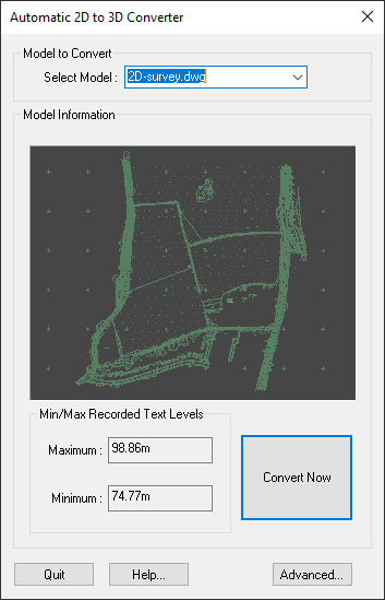
In most cases, all you need to do is press the big Convert Now button. The resultant 3D model and surface will be displayed in the 3D View window.
As Site3D can have multiple models (for exmaple, several imported files) loaded in a single project, you have the option to choose which model you wish to convert.
By default, the current survey is selected.
Note: If you want to redo the conversion (for example, with different advanced options), simply choose the orignal 2D survey model from the drop-down list. The re-conversion of the 2D model will replace the previous 3D model result.
There is an Advanced button with which you can choose special conversion options. For most typical survey drawings you will not need to use the advanced optoins, as Site3D tries to choose the best settings automatically, but sometimes you can further improve the result by adjusting the advanced options.
A Block is a drawing item that is defined once but inserted many times on the drawing at different places. For example, it is common for a cross symbol to be defined as a Block and then inserted at every level point on the survey drawing (near a level text).
As well as Point Entity features, Site3D uses Block Insertion Points as potential points for assigning a level to. Site3D automatically selects common cross-like Blocks by default.
However, you may select any of the drawing's Blocks yourself which you think should be used for level assignment.
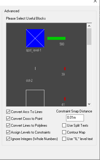
The blocks are all displayed in a scrollable window. The selected ones are those with the bright blue square background. You can select or deselect a block by clicking on its image in this window.
To assist you in your decision, the quantity of insertions of each block is shown next to the block. There is also a green bar which represents the percentage of block insertions which the item represents out of all the block insertions on the drawing. So blocks with a long green bar are more likely to be the useful ones that you need to select.
Arc entities cannot be assigned varying 3D levels in most CAD systems.
If this option is selected Site3D will convert Arc entities into small Line segments which can then be used for level assignment.
It is desirable to assign levels to the line features on the drawing, because then those lines are used in the surface triangulation to determine the surface break directions. These lines are known as constraint lines. (Default is ON).
If selected, Site3D will convert any two lines of similar length, that cross perpendicularly, to a single point. These points can then be used for assigning 3D levels to from nearby level texts. (Default is OFF unless there are very few other Insertion Points on the drawing).
If selected, Site3D will join any linked Line Entities together to form one single Polyline Entity. This allows Site3D to interpolate levels along constraint lines that do not have any level texts in the middle. (Default is ON).
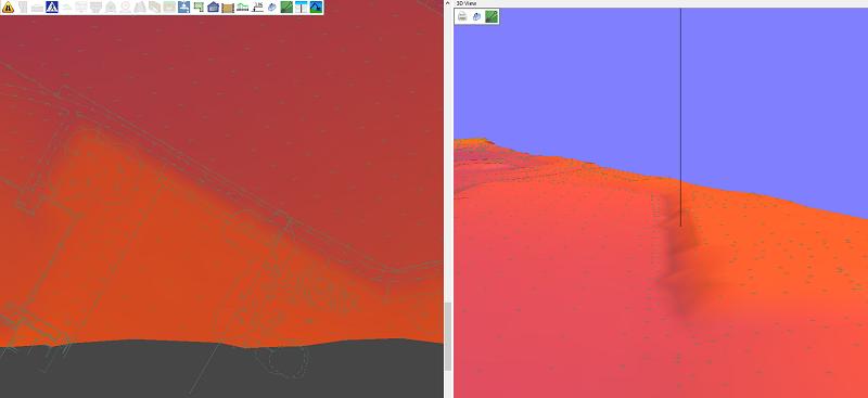
If selected, Site3D will interpret the 2D linework into 3D lines in conjunction with the interpreted 3D levels to make surface constraint lines to precisely define the 3D model. (Default is ON).
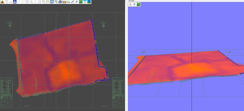
The above example shows the result of converting the 2D survey with the Assign Levels to Constraints option ON. You can see the crisp definition of the surface where the 2D linework has been intelligently interpreted into break lines for the 3D surface.
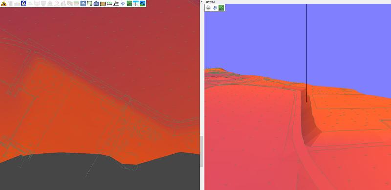
This second example shows the result of converting the 2D survey without the Assign Levels to Constraints option. You can see the surface is much less well defined with just the point cloud of 2D to 3D converted points.
If selected, Site3D will only use level texts that include decimal places. Usually level texts are not round numbers and so is not desirable to include them in your 3D ground surface as they are more likely numbers describing other features such as plot numbers etc, but sometimes you may want to include these levels in your 3D model. (Default is ON).
Site3D will assign levels from Insertion Points to the points on a nearby Polyline entity. This will give the final converted survey crisp constraints around items such as ditches and roads, (Default is ON).
If selected, Site3D will use level texts that have been split into two (or three) texts: the 'whole number' (the part before a decimal place), an optional decimal point text, and the fractional number (the part after a decimal place).
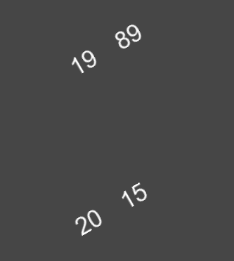
For example, in the above drawing extract which contains four individual texts, the texts “19” and “89” will be interpreted as level 19.89, and the texts “20” and “15” will be interpreted as level 20.15. (Default is OFF).
If selected, Site3D will assign a level to the entire length of the nearest polyline. Only use this option if the 2D survey drawing comprises mainly contour lines with level texts. (Default is OFF).
If selected, Site3D will use level texts that include the characters “IL”. Usually the IL denotes an Invert Level (the bottom of a manhole) and so is not desirable to include for your 3D ground surface, but sometimes you may want to include these levels in your 3D model. (Default is OFF).