This facility calculates the cut and fill volumes between two surfaces, or the volumes of one surface to a given level.
Note: To compare two surfaces you will need to have more than one surface model in the project. You may have loaded the first surface when you started the project by opening a ground survey (for example, from a DWG or DXF file). Additional surfaces can be added to the project using the Import option on the File menu. Or you may have created the Final Surface or Formation Surface from your design model.
To access the Surface Volumes window click on the Surface Volumes button ![]() on the Surfaces and Volumes toolbar
on the Surfaces and Volumes toolbar ![]() .
.
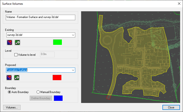
The following window is displayed for selecting the two surfaces, or surface and level, for the volume calculation:
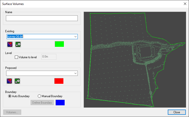
If comparing two surfaces, select each of the two surfaces from the drop-down list of available surfaces. The existing surface is initially pre-set with the current survey model.
The Proposed surface is displayed on the preview with a red boundary. The Existing surface is displayed with a green boundary.
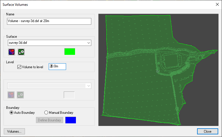
If comparing one surface to a level, select the surface from the Existing drop-down list of available surfaces, and select the Volume to level option and enter the desired level.
In this case the cut volume will be where the surface is above the given level, and the fill volume is where the surface is below the given level.
For example, if you are analysing the water volume of a flood plain, enter the flood water level. The fill volume will be the water volume over the surface.
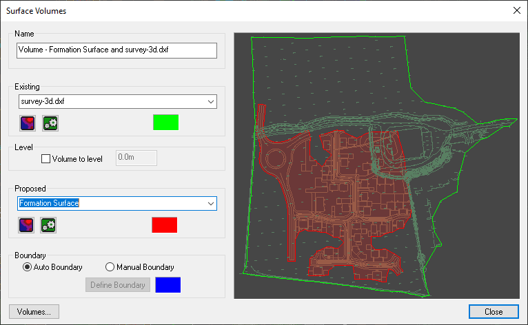
By default an auto-boundary is calculated which includes the overlapping areas of the two surfaces.
The overlapping region will be shown shaded in either red, green or yellow.
If the proposed surface is contained entirely within the existing surface, it is shaded in red:
If the existing surface is contained entirely within the proposed surface, it is shaded in green.
Whereas, if the two surfaces only partially overlap then the common region will be shaded in yellow:
The yellow shading alerts you that your proposed design extends outside the existing survey region. The proposed design region that is outside the existing survey will not contribute to the volume calculation. It is easy to see parts that won't be included because they have the red line boundary rather than the yellow.
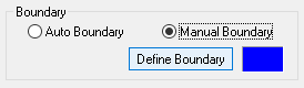
You may want to specify your own boundary to limit the region for the volume calculation. In this case select the Manual Boundary option and click the Define Boundary button.
Clicking the Define Boundary button will return you to the main plan-view window to allow you to select or create a boundary line. Click to place points to define your manual boundary. You can also make use of the snap tools and undo facility.
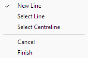
Alternatively you can pick a boundary line from one of the imported drawings. Right-click and choose Select Line from the menu.
When you have completed the boundary, right-click and select Finish from the menu.
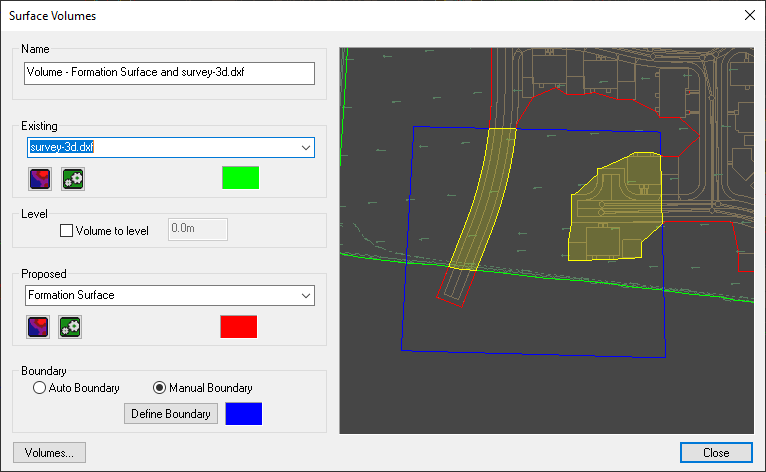
When you have finished, the Surface Volumes window will reappear showing the defined boundary shown in blue. The region common to the two surfaces and the boundary will be shaded in yellow:
To view some properties of each of your two selected surfaces click the ![]() surface properties button.
surface properties button.
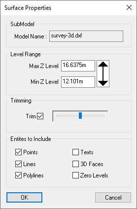
The Surface Properties window shows the maximum and minimum levels of the surface. This can be useful for verifying which is in Cut and which is in Fill.
You can modify the maximum and minimum levels which are used for the surface. Restricting the level range can be used to exclude high or low drawing features from the surface. This may reduce the outer boundary line, but it will not produce holes inside the surface.
To give a complete volume comparison between the two surfaces, one surface should be entirely contained within the other, i.e. their boundaries should not overlap.
Accordingly, it can sometimes be useful to adjust the trimming to maximize the boundary of the larger surface (often the existing ground surface), or minimize the boundary of the smaller surface (often the proposed surface).
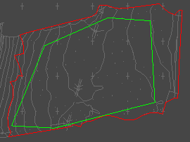
In this example, Surface 1 (red boundary) is shown with default trimming, and there is some overlap with the Surface 2 (green boundary) along the southern edge.
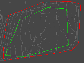
With trimming reduced on Surface 1 there is now no overlap of the two surface boundaries.
Click the Volumes... button to see the Cut and Fill volumes calculation result:
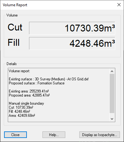
The Cut volume is where the proposed surface is lower than the existing surface.
The Fill volume is where the proposed surface is higher than the existing surface.
The volumes calculated by Site3D are the exact geometrically calculated volumes between the two surfaces. Site3D does not use approximate voluming methods.
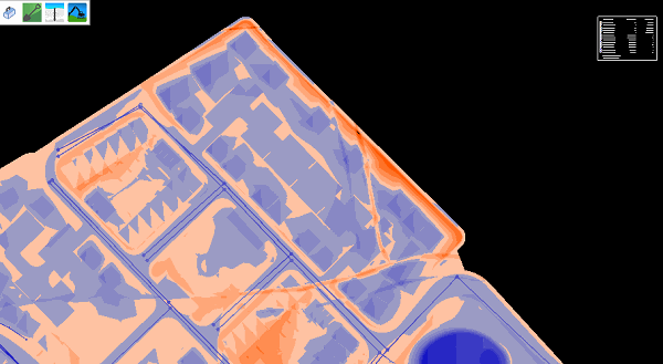
To produce the isopachyte depth model of the cut and fill, click the Display as Isopachyte... button.
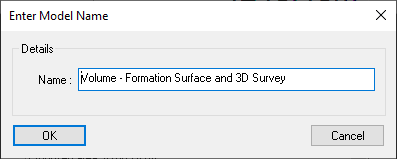
You can choose a name for the cut and fill model. When you click OK the new isopachyte surface will be saved and added to the list of models in your project.
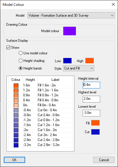
The saved volume model is automatically shaded with cut and fill height bands and the key is added to the drawing.
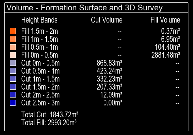
The height band key on the drawing shows the total cut and fill volumes from the calculation, as well as the cut and fill volume in each depth band:
The volume model is generated with appropriate default height banding options, and if you want to change the height band properties you can do this through the Model Colours Window: