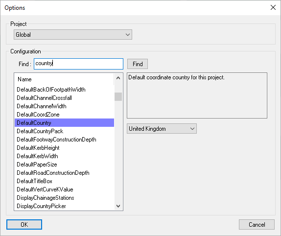
The Options window shows configuration values for the current open project, or the global defaults if no projects are open.
Note: Many Site3D project settings can be set in a more user friendly way from specific property windows, for example the Project Options Window and the Section View Display Properties Window.
To access the Options window click the Tools->Options... menu option.
Choose from the drop-down menu whether to edit settings for a particular project, or your global settings. If you have one or more projects open, you can choose which one to edit the configuration for.
The Global settings are the default settings that will be used the next time a new project is created. Changing the global settings will generally have no affect on an existing project.
Your entire organisation can use a single configuration file so that you all use the same settings.
To achieve this is quite straight forward; one user configures their global settings the way that is wanted for the whole organisation, then their configuration file is copied to a shared folder that everyone can access (for instance, on a network drive).
Here is the step-by-step process to do it:
To utilise the enterprise configuration, each user need only set the one global EnterpriseOptionsPath setting, like this:
If you subsequently want to update the enterprise configuration, you would need to first copy the Site3D-enterprise.ini file back to the Site3D-user.ini in the %appdata%\Site3D folder for the user. This must be done when Site3D is not open. Then simply do the above procedure again, updating the settings as desired, and copying back to the Site3D-enterprise.ini file in the shared folder.
On the left of the window is a list containing all the settings that can be altered.
Above the list is a search box that you can type in to quickly find a setting. As you type, a setting which contains the text will highlight.
Pressing the Find button will jump to the next setting which contains the text in the search box. Holding down the Shift key when you press the Find button will search in the reverse direction.
Selecting an item from this list will display a description of the selected setting, shown in a box to the right. Under the description the current value is displayed, this can be set as appropriate for your usage.
Here is the complete list of the currently configurable settings:
| Setting | Description | Data Type/Range | Default value |
|---|---|---|---|
| 3DViewBackGroundColour | Background colour of the 3D view. | RGB Colour | (128, 128, 255) |
| 3DViewFont | Font to use for 3D view texts. | Font | Arial |
| 3DViewSeparateFrame | Open the 3D view in a separate window from the main program. For example, to place it on a second screen. | Enabled / Disabled | Disabled |
| AllowOnlineUpdateCheck | Every time the application is run, check for updates once after loading. | Enabled / Disabled | Enabled |
| AutoSaveToLocalDrive | Auto-save the project to the local drive rather than the project folder. This is useful if the project folder is on a slow network location. | Enabled / Disabled | Disabled |
| CompanyEmployeeName | Name of user to include in reports. | Text | |
| CompanyName | Company name to include in reports. | Text | |
| ConcreteProtectionDepthUnderDesign | Minimum depth under design surface before concrete protection is required above the pipe. Depth is surface level to soffit level. | Depth | 1.2m |
| ConcreteProtectionDepthUnderSurvey | Minimum depth under survey surface before concrete protection is required above the pipe. Depth is surface level to soffit level. | Depth | 0.9m |
| ConduitAnnotationHeight | Text height for conduit annotations in the plan view. | Height | 0.75m |
| ConstructionDepthBuildingPad | Construction depth under building pads. | Depth | 0.450m |
| ConstructionDepthEarthworks | Construction depth under earthworks and ponds, including their interfacing slopes and steps. | Depth | 0.0m |
| ConstructionDepthInterfacing | Construction depth under road and footpath interfacing slopes and steps. | Depth | 0.0m |
| ConstructionDepthRBTInnerIsland | Construction depth under roundabout inner islands. | Depth | 0.2m |
| ConstructionLineColour | Colour of construction lines. | RGB Colour | (72, 146, 247) |
| CrossSectionBoxHeight | Height of annotation rows in cross-section views. | Height | 2.5m |
| CrossSectionTextHeight | Text height for text drawn in the cross section view. To use this setting, CrossSectionUseManualTextHeight must be enabled. | Height | 0.5m |
| CrossSectionUseManualTextHeight | Whether to use the manual cross section text height. If disabled the text height will be automatically calculated based on the row height. | Enabled / Disabled | Disabled |
| DefaultBackOfFootpathCrossfall | Default footway crossfall when creating a new road. | Gradient, 1 in: | -40.0 |
| DefaultBackOfFootpathWidth | Default back of footway offset when creating a new road. | Offset from channel | 1.8m |
| DefaultChannelCrossfall | Default channel crossfall when creating a new road. | Gradient, 1 in: | 40.0 |
| DefaultChannelWidth | Default channel offset when creating a new road. | Offset from centreline | 2.4m |
| DefaultCoordZone | Default coordinate zone for this project. | Drop-Down Selection | OS Grid1 |
| DefaultCountry | Default coordinate country for this project. | Drop-Down Selection | United Kingdom1 |
| DefaultCountryPack | Default country pack for this project. | Drop-Down Selection | United Kingdom1 |
| DefaultFootwayConstructionDepth | Default construction depth under footway when creating a new road. | Depth | 0.2m |
| DefaultKerbHeight | Default kerb height when creating a new road. | Height | 0.125m |
| DefaultKerbWidth | Default kerb face offset when creating a new road. | Offset from channel | 0.012m |
| DefaultRoadConstructionDepth | Default construction depth under carriageway when creating a new road. | Depth | 0.45m |
| DefaultVertCurveKValue | Whether the longsection annotates curve using K values. Otherwise, R values will be shown. | Enabled / Disabled (K values / R values) |
Disabled |
| DisplayChainageStations | Use stations instead of chainages. | Enabled / Disabled | Disabled |
| DisplayCountryPicker | Show the country picker window when the application is run. | Enabled / Disabled | Enabled |
| DisplayUnits | Units that the project will display. | Metric/US Imperial | Metric1 |
| DrainageAreaAssignedLines | Draw lines from drainable areas to their assigned conduits. | Enabled / Disabled | Disabled |
| DrainageAutoLevelForceFoulBelowStorm | Auto Level: Force foul pipes below storm pipes, even if there was clearance above the storm. | Enabled / Disabled | Disabled |
| DrainageAutoLevelFoulHorizOffset | When auto-levelling a foul drainage network, the horizontal distance within which the AutoLevelFoulZOffset value applies | Offset | 7.0m |
| DrainageAutoLevelFoulZOffset | When auto-levelling a foul drainage network, the minimum vertical separation the foul pipes should be below the storm pipes when closer than the AutoLevelFoulHorizOffset horizontal offset. | Offset | 0.3m |
| DrainageAutoLevelMaxGrade | The steepest gradient permitted for drainage pipes when auto-levelling a drainage network. | Gradient, 1 in: | 10.0 |
| DrainageAutoLevelStormPipeSizeGradients | When auto-levelling a storm drainage network, a series of rules to determine the minimum gradient required for the pipe diameter. | Rules of Pipe Diameter to Gradient | <=100=100,<=150=150,<=225=170,<=300=240,<=375=320,<=450=400,<=525=490,<=600=580,<=675=670,<=750=760,<=825=860,<=900=960,<=975=1060,<=1050=1160,>1050=1160 |
| DrainageClashDetectionManholeOffset | Minimum offset between an adoptable pipe and manhole before being considered as a clash. Offset is calculated from pipe collar to manhole external wall. | Offset | 0.2m |
| DrainageClashDetectionPipeOffset | Minimum offset between adoptable pipes before being considered as a clash. Pipe offset is calculated from collar to collar. | Offset | 0.2m |
| DrainageDepthDefault | Default depth that new adoptable drainage items are placed. | Depth | 1.2m |
| DrainageDepthPrivate | Default depth that new private drainage items are placed. | Depth | 0.9m |
| DrainageDrawPipeWidth | Draw adoptable pipes in plan view as lines drawn at the pipe diameter. | Enabled / Disabled | Disabled |
| DrainageDrawPrivatePipeWidth | Draw private pipes in plan view as lines drawn at the pipe diameter. | Enabled / Disabled | Disabled |
| DrainageFloodRiskFreeboard | Vertical distance below manhole cover level that would indicate "Flood Risk". | Depth below cover level | 0.3m |
| DrainageFoulMHNamePrefix | Foul drainage manhole name prefix. | Text | F |
| DrainageFoulUnitVolumePerDay | Foul flow per unit per day. | Litres Per Unit Per Day | 4000L |
| DrainageImportColourTest | Useful only for importing older MDX files where colour was used to distinguish private or adoptable property. Default: false. | Enabled / Disabled | Disabled |
| DrainageKerbClearanceConduit | Required clearance distance between the kerb and edge of conduit for adoptable drainage. | Offset from edge of conduit | 1.0m |
| DrainageKerbClearanceManhole | Required clearance distance between the kerb and edge of manhole for adoptable drainage. | Offset from edge of manhole | 0.5m |
| DrainageKerbClearancePrivateConduit | Required clearance distance between the kerb and edge of conduit for private drainage. | Offset from edge of conduit | 0.0m |
| DrainageKerbClearancePrivateManhole | Required clearance distance between the kerb and edge of manhole for private drainage. | Offset from edge of manhole | 0.0m |
| DrainagePrivateClashDetectionManholeOffset | Minimum offset between a private pipe and manhole before being considered as a clash. Offset is calculated from pipe collar to manhole external wall. | Offset | 0.1m |
| DrainagePrivateClashDetectionPipeOffset | Minimum offset between private pipes before being considered as a clash. Pipe offset is calculated from collar to collar. | Offset | 0.1m |
| DrainagePrivateFoulMHNamePrefix | Private foul drainage manhole name prefix. | Text | PF |
| DrainagePrivateStormMHNamePrefix | Private storm drainage manhole name prefix. | Text | PS |
| DrainageRunoffCoefficient | The default summer drainage runoff coefficient to use for drainable areas. | Decimal Number | 0.75 |
| DrainageSewersType | Default drainage standard used for pipe sizing. e.g. Sewers for Adoption version. | Name of sewers standard2 | SFA 6 |
| DrainageStormDurations | List of Storm Durations with On/Off flags. | Duration (minutes) : Enabled or Disabled |
15:0, 30:1, 60.0:0, 120:0, 180:0, 240:0, 360:0, 480:0, 600:0, 720:0, 960:0, 1440:0, 2160:0, 2880:0, 4320:0, 5760:0, 7200:0, 8640:0, 10080:0 |
| DrainageStormMHNamePrefix | Storm drainage manhole name prefix. | Text | S |
| DrainageStormReturnPeriods | List of Storm Return Periods with On/Off flags. | Return period (years) : Climate change (%) : Enabled or Disabled |
1:0:0, 2:0:0, 5:0:1, 10:0:0, 30:0:0, 100:0:0, 100:40:0, 1000:0:0 |
| DrainageStormSummerWinterFlags | Summer/Winter Storm (Summer=1, Winter=2, Both=3). | One of the following: 1 (Summer), 2 (Winter), 3 (Both) |
1 |
| DrainageTimeOfEntry | Catchment Time of Entry in minutes. | Minutes | 5.0 |
| DrainageTrenchConduitMargin | Margin added to be cut out for the drainage trenches either side of a pipe. | Offset from edge of conduit | 0.15m |
| DrainageTrenchDepthUnderManhole | Additional depth added under manholes when cutting out the drainage trenches. | Depth | 0.225m |
| DrainageTrenchDepthUnderPipe | Additional depth added under pipes when cutting out the drainage trenches. | Depth | 0.15m |
| DrainageTrenchManholeMargin | Margin added to be cut out for the drainage trenches around a manhole. | Offset from edge of manhole | 0.15m |
| DrainageWinterRunoffCoefficient | The default winter drainage runoff coefficient to use for drainable areas. | Decimal number | 0.84 |
| DraingeReportShowNetworkDetails | Include the Network Details section in the drainage report. | Enabled / Disabled | Enabled |
| DrawCentrelineDirection | Display design line direction arrows in plan view. | Enabled / Disabled | Disabled |
| DrawChannelItems | Display channel items in plan view. | Enabled / Disabled | Disabled |
| DriveOnLeft | Whether vehicles drive on left side of road. Otherwise, vehicles drive on right side of road. | Enabled / Disabled (Drive on Left / Right) |
Enabled1 |
| EnterpriseOptionsPath | Folder path to the INI file for your corporate wide options. | Folder Location | |
| EstroadVersion | Version number of the application. | Read Only | |
| ExportAs2DLevel | The level used when exporting drawings as a 2D DWG/DXF file. | Level | 0.0 |
| FormationIncludeBuildingPads | Whether the formation surface should include building pads when created. | Enabled / Disabled | Enabled |
| FormationIncludeDrainageTrenches | Whether the formation surface should include drainage trenches when created. | Enabled / Disabled | Enabled |
| FormationIncludeEarthworks | Whether the formation surface should include earthworks when created. | Enabled / Disabled | Enabled |
| FormationIncludePaths | Whether the formation surface should include paths and driveways when created. | Enabled / Disabled | Enabled |
| FormationIncludePlotBoundaries | Whether the formation surface should include plot boundaries when created. | Enabled / Disabled | Enabled |
| FormationIncludeRoads | Whether the formation surface should include roads and their attached footways when created. | Enabled / Disabled | Enabled |
| FormationIncludeRoundabouts | Whether the formation surface should include roundabouts when created. | Enabled / Disabled | Enabled |
| Gradient1InXDecimalPlaces | The number of decimal places to show whenever a gradient is annotated in the form “1 in X”, or “1 / X” or “1 : X”. | 0-16 | 0 |
| GradientEntryPreferPercent | When the user is prompted to enter a gradient, should it prompt in the form “1 : X” or as a percentage. | Enabled / Disabled | Disabled |
| GradientPercentDecimalPlaces | The number of decimal places to show whenever a gradient is annotated as a percentage. | 0-16 | 1 |
| GullyMaxMoveDistanceCrossing | Maximum distance a gully will move if within a vehicle or pedestrian crossing. | Distance | 10m |
| HorizontalAlignmentStyle | Annotation style for longsection horizontal alignment. | One of the following: 0 (Text Only), 1 (Display Curves), 2 (Display Lines), 3 (Display Curves and Lines) |
0 |
| HouseSettingOutLabelMethod | The labelling method used for the house setting out points. | One of the following: 0 (House item label), 1 (Numbered, per insert), 2 (Numbered, globally) |
0 |
| HouseSettingOutLabelShownInPlan | Whether to show the setting out point labels in plan view instead of the external wall levels. | Enabled / Disabled | Enabled |
| HouseSettingOutShowLevelColumn | Whether to show the external wall levels in the house setting out table. | Enabled / Disabled | Disabled |
| HouseSettingOutShowTemplateName | Whether to show the house template name in the title of each house setting out table. | Enabled / Disabled | Enabled |
| HouseTypeLibraryFolder | House type library folder. | Folder Location | |
| InvertMouseWheel | Invert mouse wheel zoom direction | Enabled / Disabled | Enabled |
| JunctionDimensionAnnotationHeight | Text height for junction dimension annotations in the plan view. | Height | 1.5m |
| LayerNameLookupFile | Layer name lookup filename | File Location | |
| LayersDlgSortAscending | Order the layers window by ascending value within the sorting column. Otherwise the layers will be sorted by descending value. | Enabled / Disabled (Ascending / Descending) |
Enabled |
| LayersDlgSortColumn | The column used for ordering the layers in the layer window. Represented by the column number from left to right. | One of the following: 0 (Layer Index), 1 (Name), 2 (Display), 3 (Colour) |
1 |
| MRUPrinter1 | The most recently used printer. | Printer Information | |
| MRUPrinter2 | The second most recently used printer. | Printer Information | |
| MRUPrinter3 | The third most recently used printer. | Printer Information | |
| MRUPrinter4 | The fourth most recently used printer. | Printer Information | |
| MRUPrinter5 | The fifth most recently used printer. | Printer Information | |
| ManholeAnnotationHeight | Text height for manhole annotations in the plan view. | Height | 0.75m |
| ManholeSizeOptions | List of manhole size choices with max pipe diameter. | Rules of Pipe Diameter to Manhole Size | <375=1200 <=450=1350 <=700=1500 <=900=1800 >900=+900 |
| MiddleButtonExtents | Double click middle mouse button to zoom to extents. | Enabled / Disabled | Enabled |
| NetworkLicenseServer | Network license server. | Name of network license server or network location | |
| OrdnanceSurveyContours | Path to Ordnance Survey Contour data | Folder Location | |
| OrdnanceSurveyMeridian2 | Path to Ordnance Survey Meridian 2 data | Folder Location | |
| OrdnanceSurveyVectorMap | Path to Ordnance Survey Vector Map data | Folder Location | |
| PipeBeddingAnnotateLongsection | Annotate pipe bedding on longsections. | Enabled / Disabled | Disabled |
| PipeBeddingAnnotatePlan | Annotate pipe bedding on plan. | Enabled / Disabled | Disabled |
| PipeBeddingNameA | Text name for Type A pipe bedding. | Text | BEDDING TYPE A |
| PipeBeddingNameB | Text name for Type B pipe bedding. | Text | BEDDING TYPE B |
| PipeBeddingNameF | Text name for Type F pipe bedding. | Text | BEDDING TYPE F |
| PipeBeddingNameG | Text name for Type G pipe bedding. | Text | BEDDING TYPE G |
| PipeBeddingNameH | Text name for Type H pipe bedding. | Text | BEDDING TYPE H |
| PipeBeddingNameI | Text name for Type I pipe bedding. | Text | BEDDING TYPE I |
| PipeBeddingNameJ | Text name for Type J pipe bedding. | Text | BEDDING TYPE J |
| PipeBeddingNameK | Text name for Type K pipe bedding. | Text | BEDDING TYPE K |
| PipeBeddingNameL | Text name for Type L pipe bedding. | Text | BEDDING TYPE L |
| PipeBeddingNameM | Text name for Type M pipe bedding. | Text | BEDDING TYPE M |
| PipeBeddingNameN | Text name for Type N pipe bedding. | Text | BEDDING TYPE N |
| PipeBeddingNameS | Text name for Type S pipe bedding. | Text | BEDDING TYPE S |
| PipeBeddingNameT | Text name for Type T pipe bedding. | Text | BEDDING TYPE T |
| PipeBeddingNameZ | Text name for Type Z pipe bedding. | Text | BEDDING TYPE Z |
| PipeMaterialAnnotateLongsection | Annotate pipe material on longsections. | Enabled / Disabled | Disabled |
| PipeMaterialAnnotatePlan | Annotate pipe material on plan. | Enabled / Disabled | Disabled |
| PipeMaterialNameClay | Display name for clay pipe material. | Text | CLAY PIPE |
| PipeMaterialNameConcrete | Display name for concrete pipe material. | Text | CONCRETE PIPE |
| PipeMaterialNamePlastic | Display name for plastic pipe material. | Text | PLASTIC PIPE |
| PlanViewAutoRecoveryTime | Time interval, in minutes, between auto-recovery saves. A value of 0 will disable auto-recovery saving. | Decimal Number | 5.0 |
| PlanViewBackGroundColour | Background colour of the plan view. | RGB Colour | (70, 70, 70) |
| PlanViewFont | Font to use for plan view texts. | Font | Arial |
| PlanViewMaxSurfaceColour | Colour for the highest level shown in the plan view. | RGB Colour | (255, 89, 0) |
| PlanViewMinSurfaceColour | Colour for the lowest level shown in the plan view. | RGB Colour | (0, 0, 196) |
| PlotBoundaryAnnotateLevelDiffGravelBoards | Include the level difference in gravel board annotations. Is inserted between the gravel board prefix and suffix. | Enabled / Disabled | Enabled |
| PlotBoundaryAnnotateLevelDiffRetainingWalls | Include the level difference in retaining walls annotations. Is inserted between the retaining walls prefix and suffix. | Enabled / Disabled | Enabled |
| PlotBoundaryAnnotateUnits | For retaining walls and gravel boards that are annotating a level difference, show the units after the level difference value. | Enabled / Disabled | Disabled |
| PlotBoundaryAnnotationHeight | Text height for plot boundary annotations. | Height | 0.4m |
| PlotBoundaryAnnotationLineOffset | Plot boundary annotation offset from line. | Offset | 0.2m |
| PlotBoundaryFenceLimit | Max level difference for a plot boundary to be considered as a fence. Fences will not annotate the level difference between plots. | Level Difference | 0.0m |
| PlotBoundaryGravelBoardLimit | Max level difference for a plot boundary to be considered as gravel board. | Level Difference | 0.3m |
| PlotBoundaryGravelBoardPrefix | Prefix for gravel board level difference annotations. | Text | GB |
| PlotBoundaryGravelBoardSuffix | Suffix for gravel board level difference annotations. | Text | |
| PlotBoundaryLargeUnits | Whether large units are used for plot boundary annotation. Otherwise, small units will be used. | Enabled / Disabled (Large units / Small units) |
Disabled |
| PlotBoundaryRetainingWallPrefix | Prefix for retaining wall level difference annotations. | Text | RTW |
| PlotBoundaryRetainingWallSuffix | Suffix for retaining wall level difference annotations. | Text | |
| ProjectSaveDate | Date and time of last project save. | Date | |
| SectionAnnotatedLevels | Enable to use the top of finished surface levels when annotating centreline and channel levels in the longsection view. Otherwise, the underlying centreline/channel levels will be annotated and speedtables will have an additional annotation specifying the height offset to be added to the annotated levels. | Enabled / Disabled (Finished surface levels / Centreline levels) |
Disabled |
| SectionGradientsPreferPercentages | Bias longsection gradient annotation to annotate as percentages. Otherwise, gradient annotations will bias toward displaying as a ratio (e.g. 1 in 10). | Enabled / Disabled | Enabled |
| SectionLabelCentrelineChainage | Section view row label for centreline chainage annotation. | Text | CHAINAGE ON CENTRELINE |
| SectionLabelCentrelineLevels | Section view row label for centreline level annotation. | Text | LEVELS ON CENTRELINE \nOF CARRIAGEWAY |
| SectionLabelCentrelineStation | Section view row label for centreline station annotation. | Text | CENTRELINE STATION |
| SectionLabelDesignChainage | Section view row label for design line chainage annotation. | Text | DESIGN CHAINAGE |
| SectionLabelDesignLevels | Section view row label for design level annotation. | Text | DESIGN LEVELS |
| SectionLabelDesignStation | Section view row label for design line station annotation. | Text | DESIGN STATION |
| SectionLabelEarthworkLevels | Section view row label for earthwork level annotation. | Text | EARTHWORK LEVELS |
| SectionLabelExistingChainage | Section view row label for existing ground chainage annotation. | Text | EXISTING CHAINAGE |
| SectionLabelExistingLevels | Section view row label for existing ground level annotation. | Text | EXISTING LEVELS |
| SectionLabelExistingStation | Section view row label for existing ground station annotation. | Text | EXISTING STATION |
| SectionLabelFoulInvert | Section view row label for foul water manhole invert level annotation. | Text | FOUL WATER SEWER \nINVERT LEVELS |
| SectionLabelHorizontalDesign | Section view row label for centreline horizontal design annotation. | Text | HORIZONTAL DESIGN ON \nCARRIAGEWAY CENTRELINE |
| SectionLabelLeftChannelLevels | Section view row label for left channel level annotation. | Text | LEVELS ON \nLEFT HAND CHANNEL |
| SectionLabelManholeCover | Section view row label for manhole cover annotation. | Text | MANHOLE COVER \nLEVELS APPROX |
| SectionLabelManholeDiameter | Section view row label for manhole diameter annotation. | Text | MANHOLE DIAMETER |
| SectionLabelProposedChainage | Section view row label for proposed chainage annotation. | Text | PROPOSED CHAINAGE |
| SectionLabelProposedLevels | Section view row label for proposed level annotation. | Text | PROPOSED LEVELS |
| SectionLabelProposedStation | Section view row label for proposed station annotation. | Text | PROPOSED STATION |
| SectionLabelRightChannelLevels | Section view row label for right channel level annotation. | Text | LEVELS ON \nRIGHT HAND CHANNEL |
| SectionLabelSurfaceInvert | Section view row label for surface water manhole invert level annotation. | Text | SURFACE WATER SEWER \nINVERT LEVELS |
| SectionLabelVerticalDesign | Section view row label for centreline vertical design annotation. | Text | VERTICAL DESIGN ON \nCARRIAGEWAY CENTRELINE |
| SectionPipeAnnotationStyle | Annotation style used when displaying pipe information in the longsection drainage rows. If set to 0 this will annotate the pipe information as a single centred multi-line text. If set to 1, each line of annotation will be drawn as separate texts near the edges of the row. | One of the following: 0 (Multi-Line Text), 1 (Separate Texts) |
0 |
| SectionRegularIntervalsOnly | Show longsection level and chainage annotations at regular intervals only, do not add additional annotations at points of interest. | Enabled / Disabled | Disabled |
| SectionRowOrder | List of comma-separated keywords defining the order of rows on longsections. The list must include SECTION_DRAWING to determine where rows are placed relative to the section drawing. | Row IDs separated by commas3 | MANHOLE_COVER, FOUL_INVERT, SURFACE_INVERT, MANHOLE_DIAMETER, SECTION_DRAWING, EXISTING_CHAINAGE, CENTRELINE_CHAINAGE, DESIGN_CHAINAGE, CENTRELINE_LEVELS, DESIGN_LEVELS, LEFT_CHANNEL_LEVELS, RIGHT_CHANNEL_LEVELS, VERTICAL_DESIGN, HORIZONTAL_DESIGN, EXISTING_LEVELS, GROUND_SECTIONS, PROPOSED_CHAINAGE, PROPOSED_LEVELS, SUBSTRATUM, EARTHWORKS |
| SectionViewAnnotateExistingToProprosed | Annotate existing surfaces at the same chainages as proposed levels. | Enabled / Disabled | Enabled |
| SectionViewAnnotatePipeNumber | Whether to show the pipe number when annotating pipes in the longsection. | Enabled / Disabled | Enabled |
| SectionViewAnnotationBoxHeight | Height of annotation rows in longsection views. | Height | 6.0m |
| SectionViewAnnotationCentrelineChainage | Have centreline chainage as a default annotation row in the longsection view. Used in centreline longsections. | Enabled / Disabled | Enabled |
| SectionViewAnnotationCentrelineLevels | Have centreline levels as a default annotation row in the longsection view. Used in centreline longsections. | Enabled / Disabled | Enabled |
| SectionViewAnnotationChainage | Have existing chainage as a default annotation row in the longsection view. | Enabled / Disabled | Enabled |
| SectionViewAnnotationChannelLeft | Have left channel levels as a default annotation row in the longsection view. Used in centreline longsections. | Enabled / Disabled | Enabled |
| SectionViewAnnotationChannelRight | Have right channel levels as a default annotation row in the longsection view. Used in centreline longsections. | Enabled / Disabled | Enabled |
| SectionViewAnnotationExistingLevels | Have existing levels as a default annotation row in the longsection view. | Enabled / Disabled | Enabled |
| SectionViewAnnotationHorizAlignment | Have horizontal alignment as a default annotation row in the longsection view. Used in centreline longsections. | Enabled / Disabled | Enabled |
| SectionViewAnnotationVertAlignment | Have vertical alignment as a default annotation row in the longsection view. Used in centreline longsections. | Enabled / Disabled | Enabled |
| SectionViewBackGroundColour | Background colour of the longsection view. | RGB Colour | (70, 70, 70) |
| SectionViewDatum | Longsection Views Datum | Level | 8.0m |
| SectionViewDisplayChannelLines | Display channel lines on longsection views by default. | Enabled / Disabled | Enabled |
| SectionViewDisplayCompactAnnotation | Use the compact annotation style in longsection views. | Enabled / Disabled | Enabled |
| SectionViewDisplayJoiningJunctions | Annotate joining junctions on longsection views by default. | Enabled / Disabled | Enabled |
| SectionViewDisplayTangentLines | Display vertical curve tangent lines on longsection views by default. | Enabled / Disabled | Enabled |
| SectionViewFont | Font to use for longsection view texts. | Font | Arial |
| SectionViewMaxGradient | Longsection view warning threshold for the lower limit of gradient in vertical alignments. Centreline gradients flatter than this value will highlighted in red. Note: The name SectionViewMaxGradient may be misleading because the Max refers to the X in a gradient written as 1:X, rather than referring to the gradient itself. | Gradient, 1 in: | 150.0 |
| SectionViewMinGradient | Longsection view warning threshold for the upper limit of gradient in vertical alignments. Centreline gradients steeper than this value will highlighted in red. Note: The name SectionViewMinGradient may be misleading because the Min refers to the X in a gradient written as 1:X, rather than referring to the gradient itself. | Gradient, 1 in: | 10.0 |
| SectionViewSeparateFrame | Open new longsection views in a separate window from the main program. For example, to place it on a second screen. | Enabled / Disabled | Disabled |
| SectionViewTextHeight | Text height for text drawn in the longsection view. To use this setting, SectionViewUseManualTextHeight must be enabled. | Height | 1.0m |
| SectionViewUseManualTextHeight | Whether to use the manual section text height. If disabled the section text height will be automatically calculated based on the section row height. | Enabled / Disabled | Disabled |
| SectionViewVerticalExaggeration | The default vertical exaggeration factor applied to longsection views. The view will be scaled along the vertical axis by this multiplier amount. | Decimal Number | 5.0 |
| SectionYAxisAnnotationFullWidthLines | Draw horizontal grid lines on longsections at regular intervals. | Enabled / Disabled | Disabled |
| SectionYAxisAnnotationMajorColour | Colour of major interval lines for longsection Y Axis annotation. | RGB Colour | (0, 0, 0) |
| SectionYAxisAnnotationMajorInterval | The tick interval between major tick marks along the longsection Y axis. A value of 1 will make every tick interval a major interval. | Whole Number | 5 |
| SectionYAxisAnnotationMinorColour | Colour of minor interval lines for longsection Y Axis annotation. | RGB Colour | (100, 100, 100) |
| SectionYAxisAnnotationMinorInterval | The distance between tick marks/grid lines along the longsection Y axis. | Height | 1.0m |
| SectionYAxisAnnotationOn | Annotate Y axis values on longsections. Only annotates on the major interval. | Enabled / Disabled | Disabled |
| ShowMousePrompts | Show prompt messages by the mouse cursor. | Enabled / Disabled | Enabled |
| ShowTooltips | After clicking on a tool, show a tooltip explaining how to use the tool. This window appears in the top right corner of the view. | Enabled / Disabled | Enabled |
| TopsoilBackfillDepth | Depth of soil to be be backfilled in garden and verge areas. | Depth | 0.15m |
| UseCloudLicenseServer | Use a cloud license. | Enabled / Disabled | Disabled |
| UseNetworkLicenseServer | Use a network license server. | Enabled / Disabled | Disabled |
| VerticalAlignmentStyle | Annotation style for longsection vertical alignment. | One of the following: 0 (Text Only), 1 (Display Curves), 2 (Display Lines), 3 (Display Curves and Lines) |
0 |
| WidenFollowsCurveOption | Whether the deprecated Follows Curves option is shown on the Channel and Footway Widening item window. It is recommended to use a Mitre Corner item instead of the deprecated Follows Curve option. NOTE: This setting affects only the global configuration setting; it has no affect for individual project settings. | Enabled / Disabled | Disabled |
| XSectionViewBackGroundColour | Background colour of the cross-section view. | RGB Colour | (70, 70, 70) |
| XSectionViewExtentsAutomatic | Automatically calculate the vertical extents of cross section view. Otherwise, the manual height will be used instead. | Enabled / Disabled (Automatic / Manual) |
Enabled |
| XSectionViewExtentsHeight | Manual height for cross-section view extents. | Height | 210.0m |
| XSectionViewFont | Font to use for cross section view texts. | Font | Arial |
| XSectionViewOrdinates | Display of cross section view ordinates (vertical reference lines). | One of the following: 0 (none), 1 (survey), 2 (all) |
1 |
| XSectionViewSeparateFrame | Open new cross-section views in a separate window from the main program. For example, to place it on a second screen. | Enabled / Disabled | Disabled |
| XSectionViewVerticalExaggeration | The default vertical exaggeration factor applied to cross-section views. The view will be scaled along the vertical axis by this multiplier amount. | Decimal Number | 5.0 |
| ZoomOutFromCursor | Zoom the view using the mouse position as the focal point. Useful for zooming to a specific feature under the cursor. | Enabled / Disabled | Enabled |
The default values in the above table are displayed in metric units. When viewed in Site3D, the values will be shown converted using the current display units setting. Additionally, for values that are displayed with a unit, you can type a value followed by any supported unit.
1 When running Site3D for the first time the country picker window should appear. This will override the default values with the appropriate country specific defaults where possible.
2 The sewers standard name must match one of the following:
3 The ordering of longsection table rows is defined by a comma separated list of pre-defined Row ID names. Every Row ID name should be included in the list and not appear multiple times. Below is a list of the Row ID names: