This option is for specifying the horizontal design of a roundabout arm junction.
On the ![]() roundabout tools toolbar, click the
roundabout tools toolbar, click the ![]() Edit Roundabout Junction button.
Edit Roundabout Junction button.
Click near one of the arms of a roundabout to select which junction to modify. The following window is shown:
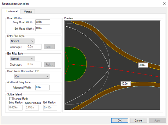
The entry/exit fillet radii are shown in boxes next to the corresponding arcs on the preview. You can enter your desired fillet radii, and the preview will update to show how the junction would look.
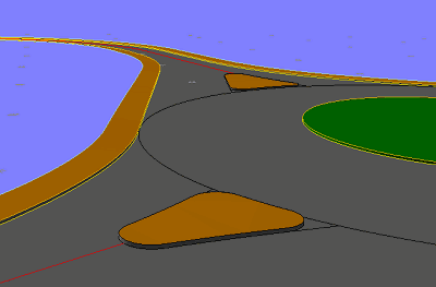
Note: You can specify a negative radius to have the roundabout junction bulge to form a smooth connection to the roundabout when a positive radius would result in an S curve:
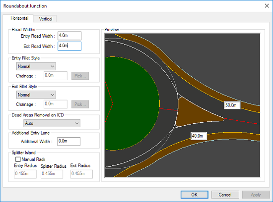
On the left the exit radius of the roundabout arm is 40m, and on the right the roundabout arm is given a -40m exit radius.
The values given for the entry and exit road widths determine whether a splitter island is formed on the junction. Where the specified entry/exit road widths are less then the available width, then a splitter island is automatically generated.
The road width at the junction is measured from the point where the roundabout circumference intersects with the road centreline, across the carriageway perpendicular to the entry/exit fillet arc.
In this example the roundabout has a 35m ICD. The fillet radius for the junction entry is 40m giving an entry road width greater than 5m. The exit radius is 50m giving an exit road width greater then 6m. Accordingly, specifying the entry width as 5m and the exit width as 6m means that a splitter island is necessary.
By default, the three corner radii on the splitter island are set automatically, as appropriate to the island dimensions.
If you want to override the automated defaults, then select the Manual Radii check-box. You may then enter your own choice of radius for each of the three corners. The effect of changing the radius is shown on the preview.
Note: The position and curvature of the sides of the splitter islands are automatically generated using engineering geometry determinant on the rest if the roundabout and joining road.
A dead area is a part of the carriageway which is rarely driven over. A dead area is undesirable because gravel and debris will tend to settle there. This can present a hazard when driven over due to the risk of throwing up stones from vehicle tyres, and there will be reduced grip for two wheeled vehicles which can slide on the debris.
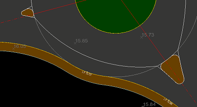
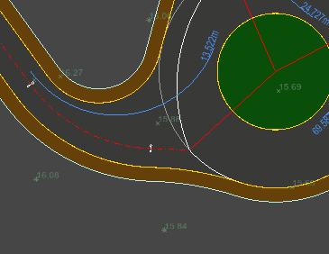
When the entry of one junction and the exit of the adjoining junction are linked by a small part of the roundabout outer circle, the kerb-line will exhibit a reverse-curve section on the roundabout.
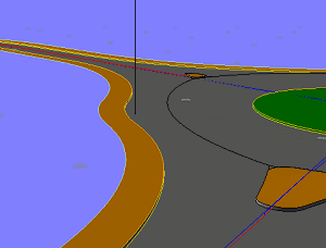
On this 3D view of the driver's path it can be seen that the reverse curve section creates a small segment of carriageway which will rarely be driven on (Marked on the diagram by the vertical black line), as vehicles will tend to drive straight from the entry to the exit without steering into the reverse curve.
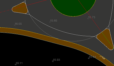
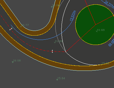
By default Site3D will automatically try to eliminate an interjunction dead area. This is achieved by placing a straight tangent line on the chord of the outer roundabout circle midway between the junctions. The junction entry/exit curves are then filleted onto this tangent line instead of onto the circle.
From the driver's perspective, it can be seen that the junction now exhibits a much improved path from entry to adjacent exit.
Automated dead area removal is determined on factors such as the angle between the adjacent junctions, length of the reverse curve chord and the size of the roundabout.
If you want to override the default dead area removal, you can choose to force it on or off. When forced on it will not always be possible for the dead area removal to be achieved (in which case a design alert symbol is placed on the drawing).
In some cases it is not geometrically possible to remove the dead area between two sequential arms. This may happen if a roundabout arm is too close to another for their specified entry/exit radii to fillet, or if the arms are too far apart. In this case a design alert will be shown on the drawing.
The default style of entry/exit is for the curve to fillet directly onto the roundabout outer circle. Sometimes it may be desirable for the entry/exit to leave the roundabout on a straight tangent and then fillet back onto the road.
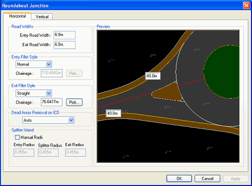
To design this type of entry/exit select the Fillet Style as Straight.
To define the direction of the straight tangent line use the Pick button and select a chainage on the road centreline. The tangent line (on the roundabout outer circle) will be constructed to pass through this point on the road centreline.
The fillet radius at the end of the tangent line (back onto the road channel) can be entered in the box shown on the preview.
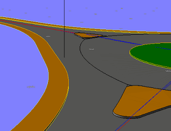
This 3D view shows the driver's view with a straight entry/exit at the roundabout junction.