Site3D exports ponds to Microdrainage when they are included in a drainage network. Specifically, a pond will be included in the exported drainage network if any manhole is located inside its plan area.
Note: Due to the modelling of ponds in Microdrainage, any pipes that flow into the pond will be need to be connected to the outfall by a conduit. These connective pipes within the pond are not intended to physically be built but are needed to join up the drainage network. It is up to the engineer to decide on the design criteria of these notional pipes to minimise additional storage without curtailing the flow.
Below is a simple example of a drainage network with a pond:
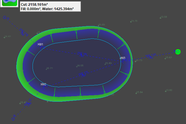
When exported to Microdrainage, the manhole that is associated with the pond will be the manhole within the pond area that is closest upstream from the out-flowing conduit.
Site3D automatically slices the pond at 10cm vertical intervals, exporting the plan area of each slice to define the storage volume at varying water levels.
Below is the above drainage network exported from Site3D when viewed in Microdrainage:
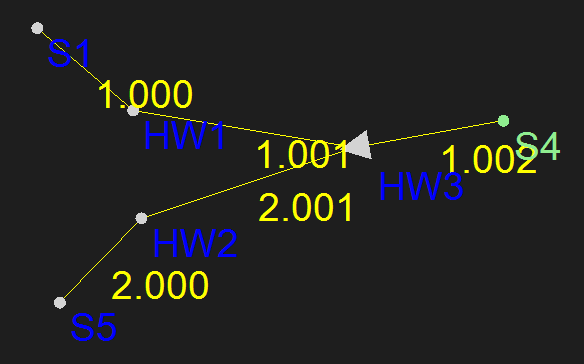
The pond is associated with the manhole labelled HW3 and flows through to pipe 1.002.
Ponds in Microdrainage are modelled by circular areas at specified levels, forming conical volumes.
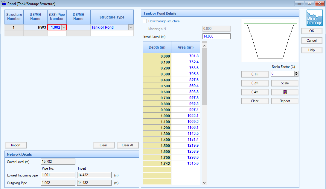
Above you can see how the pond data appears in Microdrainage after being exported from Site3D.