This option is for viewing and designing the vertical alignment for a road.
On the ![]() road tools toolbar in a plan view, click the
road tools toolbar in a plan view, click the ![]() road vertical alignment button.
road vertical alignment button.
You will be promtped to select a road from the drawing. As you move the mouse cursor the nearest road centreline is highlighted. Click to select. The road's longsection is shown in a new window along the bottom of the screen.
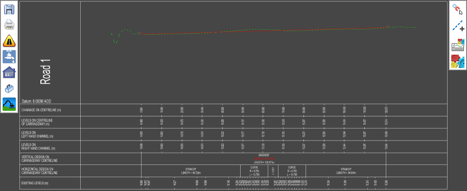
The section drawing is fully constructed with levels and chainages annotated in tables below the section lines. These tables will automatically update whenever the design is modified in vertical or plan.
The section through the existing ground survey is drawn as a green line. The road centreline section is in red.
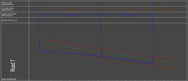
If a storm and/or foul drainage system has been added to the design, that is also shown, with annotation in a table above the section lines.
On the left edge of the view is the design toolbar and longsection design tools.
![]() Save the current longsection to a DXF/DWG file
Save the current longsection to a DXF/DWG file
![]() Print/plot the longsection
Print/plot the longsection
![]() or
or ![]() Centreline vertical tools
Centreline vertical tools
![]() Drainage vertical tools
Drainage vertical tools
![]() House vertical tools
House vertical tools
![]() Toolbox tools
Toolbox tools
![]() Earthwork vertical tools
Earthwork vertical tools
On the right edge of the view is the view toolbar. This contains the snaps tools, construction line tools, and view properties buttons.
![]() Change the snap mode for the Long-Section tools
Change the snap mode for the Long-Section tools
![]() Add construction lines to the Long-Section
Add construction lines to the Long-Section
![]() Edit the properties of the current Long-Section
Edit the properties of the current Long-Section
![]() Edit display properties for all Long-Section
Edit display properties for all Long-Section
By default, the centreline vertical tools will be open. These tools allow you to design the vertical alignment of the centreline.


![]() Add a Vertical IP (Intersection Point) into the Road Centreline
Add a Vertical IP (Intersection Point) into the Road Centreline
![]() Fillet a Vertical IP with a Parabolic Curve
Fillet a Vertical IP with a Parabolic Curve
![]() Move a Vertical IP
Move a Vertical IP
![]() Delete a Vertical IP
Delete a Vertical IP
![]() Allows you to select a surface to level the centreline onto
Allows you to select a surface to level the centreline onto
![]() Edit properties of the road
Edit properties of the road
![]() Click this button to close the Road toolbar
Click this button to close the Road toolbar